
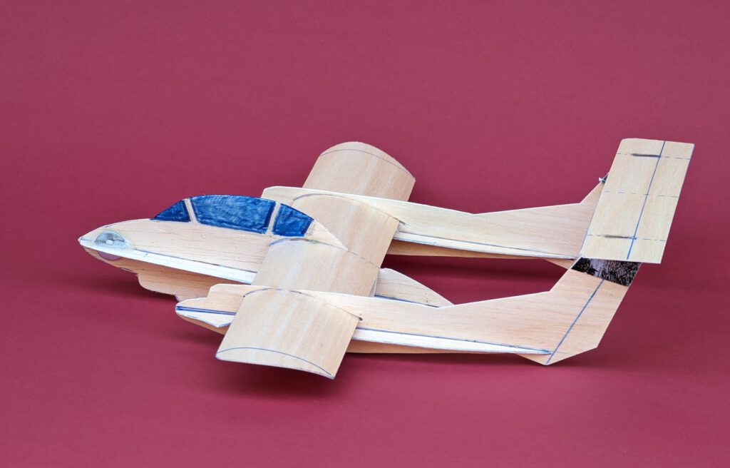
Span 30.5 cm / 12 in
Weight 24 g / 0.85 oz
The original aircraft was a one-and-only-prototype that first flew in 1964. It was planned as a cost effective close air support plane capable of operating from roads close to battlefields as well. The Convair Charger had very short wings but full-span trailing-edge slotted flaps, leading-edge slats and a full moving tailplane. Features that provided for short take-off and landing runs. The twinseat aircraft was powered by two Canadian Pratt & Whitney turboprop engines developing 650 hp each. Span was 8.38m / 27 ft 6 in later enlarged to 9.18 m / 30 ft 1 ¼ in and length 10.62 m / 34 ft 10 in. Armament consisted of four machine guns and hardpoints for bombs and/or rockets. The rival of the Charger which won the competition for a Light Armed Reconnaissance Aircraft later being used by the U.S. Marines, Army and Air Force was the widely known OV-10 Bronco from North American Aviation. Lifespan of the unique Convair Charger was rather short as it crashed on its 196th testflight in November 1965.
For stunning inflight impressions of the real-thing Charger visit YouTube!
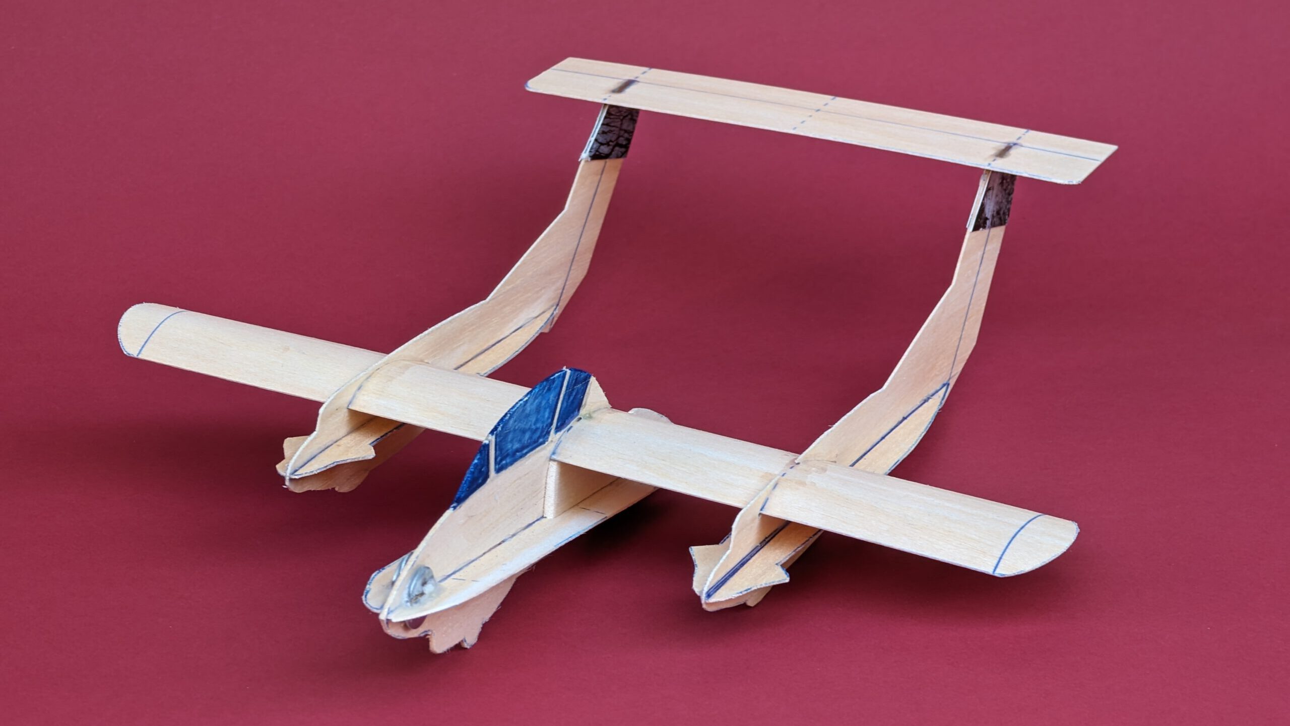
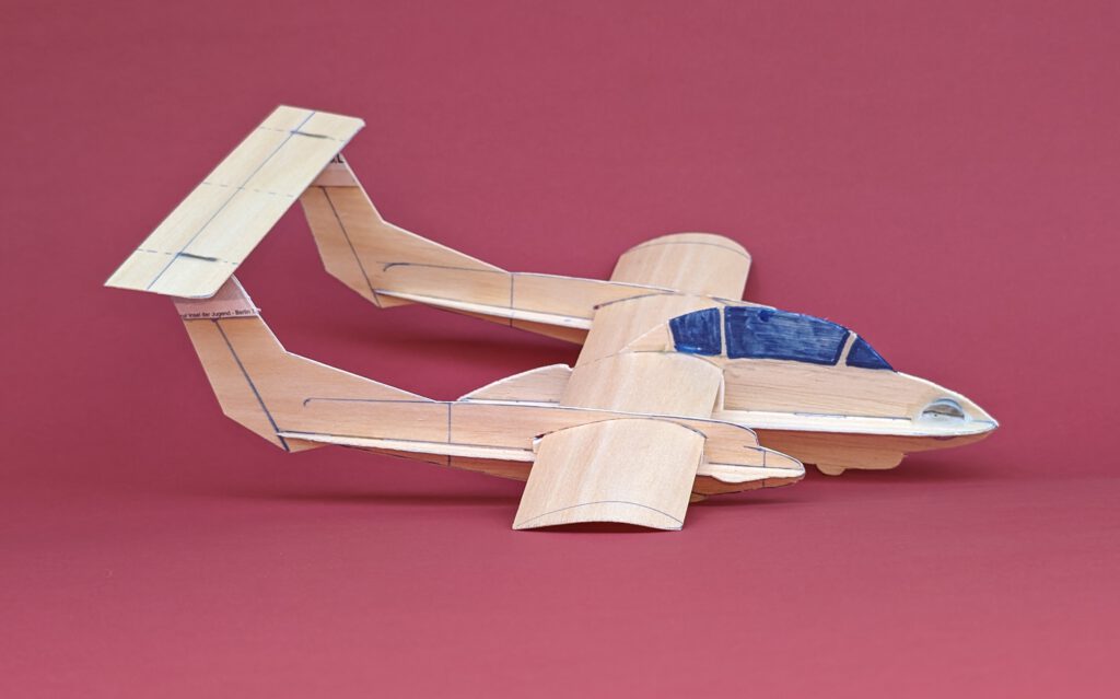
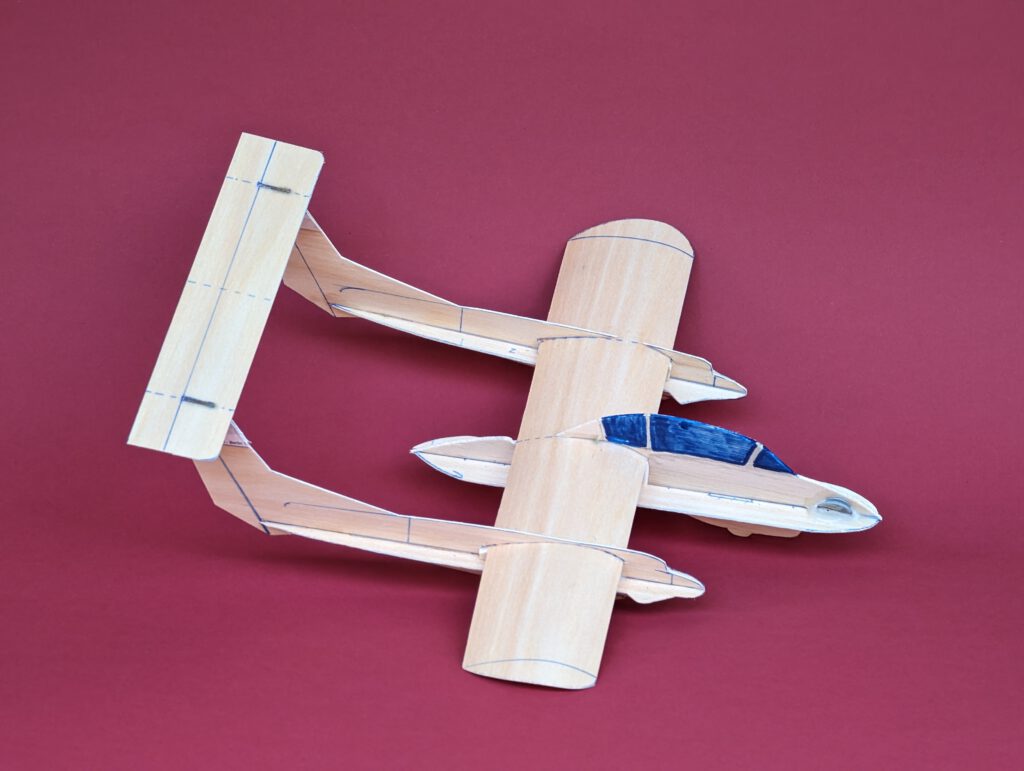
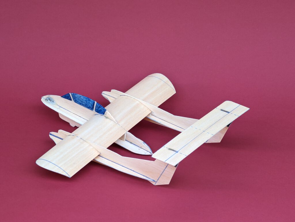
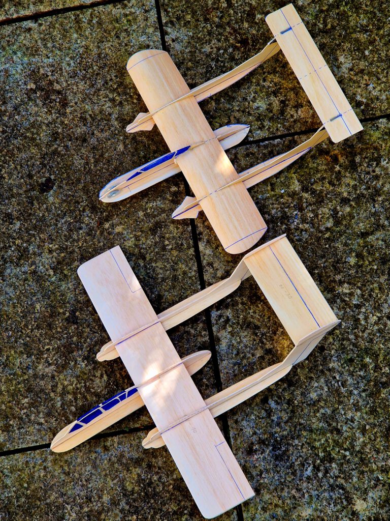
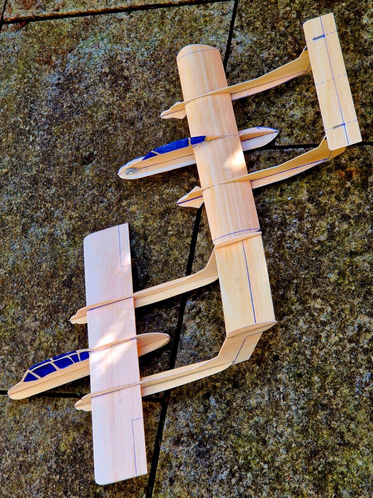
Building the balsa sheet chuck glider Convair Charger.
Note:
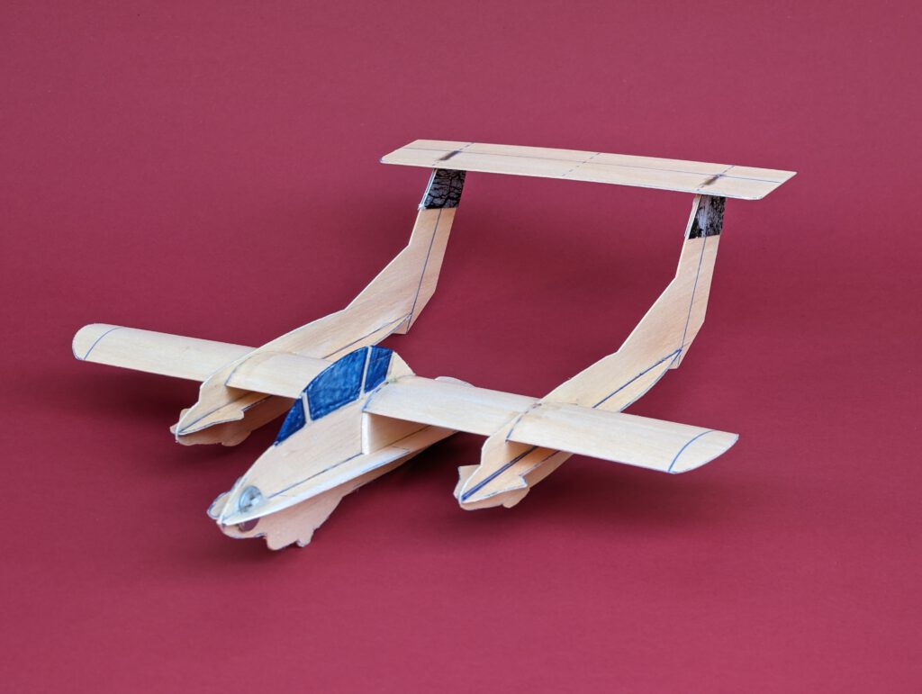
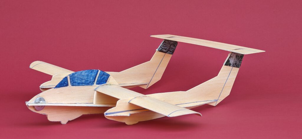
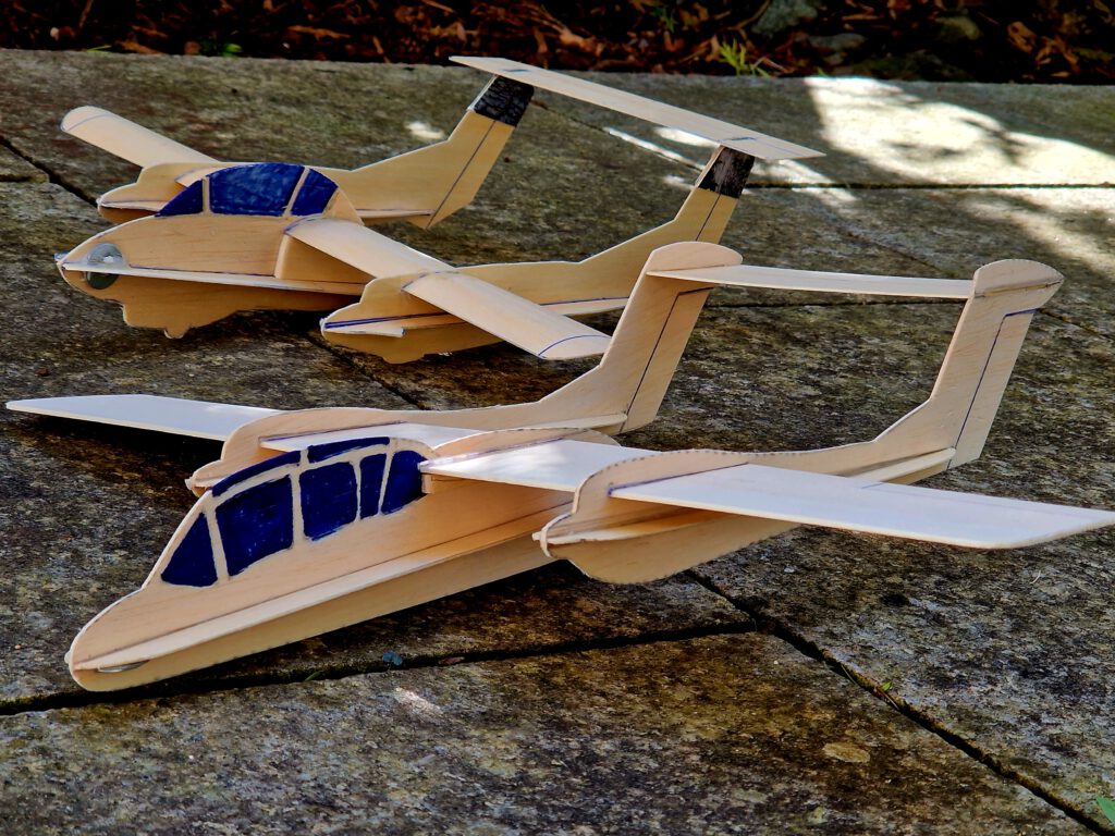
Within the range of my plans you will find one of the OV-10 Bronco as well. Both models (photos) are comparable in size but have totally different wing layouts and thus different flying patterns. Best build both models to find out which flies better!
Materials:
Fuselage gondola: B 1.5; Fuselage gondola side stiffener: B 1; booms: B 0.8 or B 1; boom stiffeners: B 0.8; wing supports: B 2; wings: B 1; horizontal stabilizer: B 0.8 or B 1; horizontal stabilizer attachment: bent paperclip/steel wire and a piece of copy paper; ballast: small piece of lead or scrap metal.
Assembly:
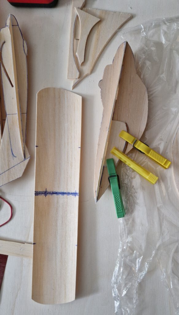
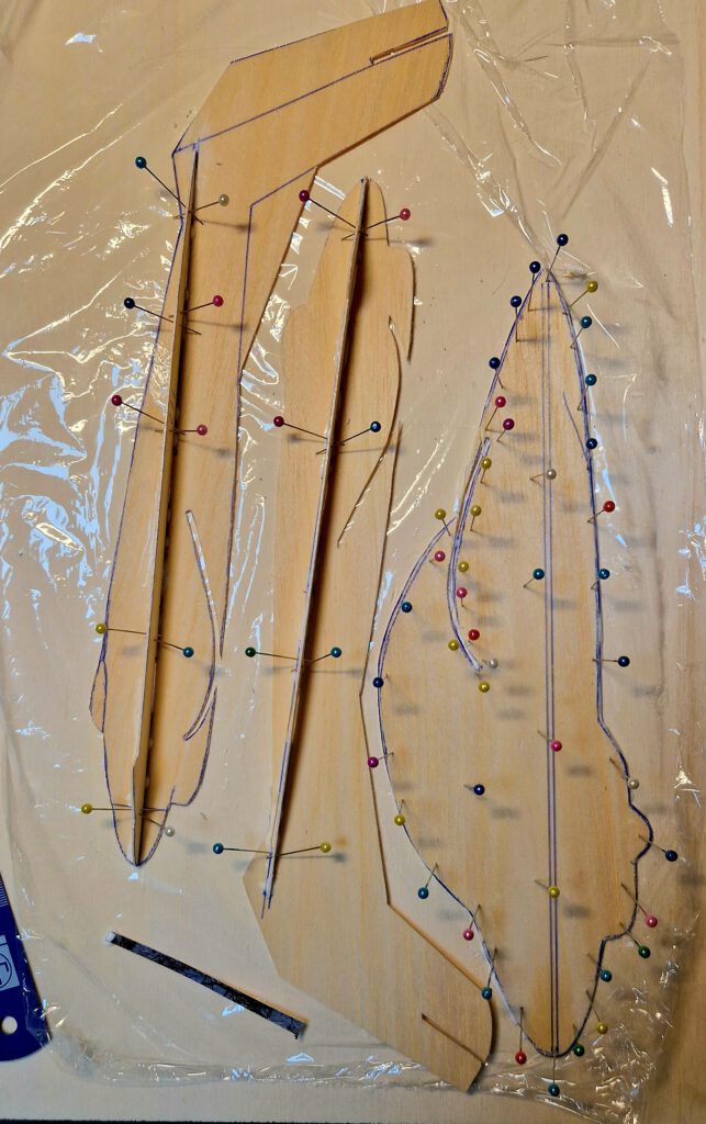
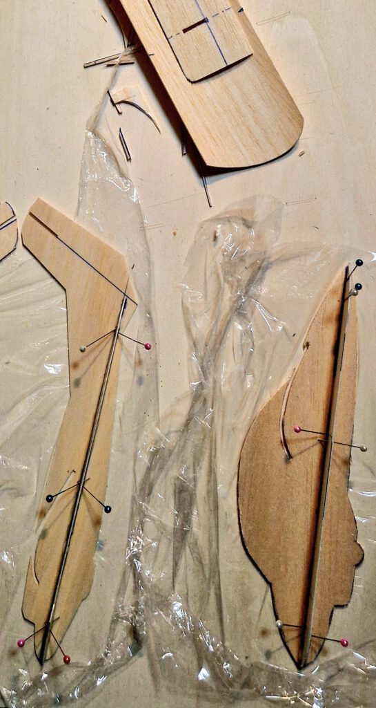
Cut out all balsa parts. Make slots for wing, stiffeners and horizontal stabilizer. Sand well. Transfer outlines of cabin, rudders, elevators flaps etc. from paper to wood with pen.
Wing:
Hold convexly curved wing evenly over hot steam until it has definitely changed its shape. Let dry.
Fuselage:
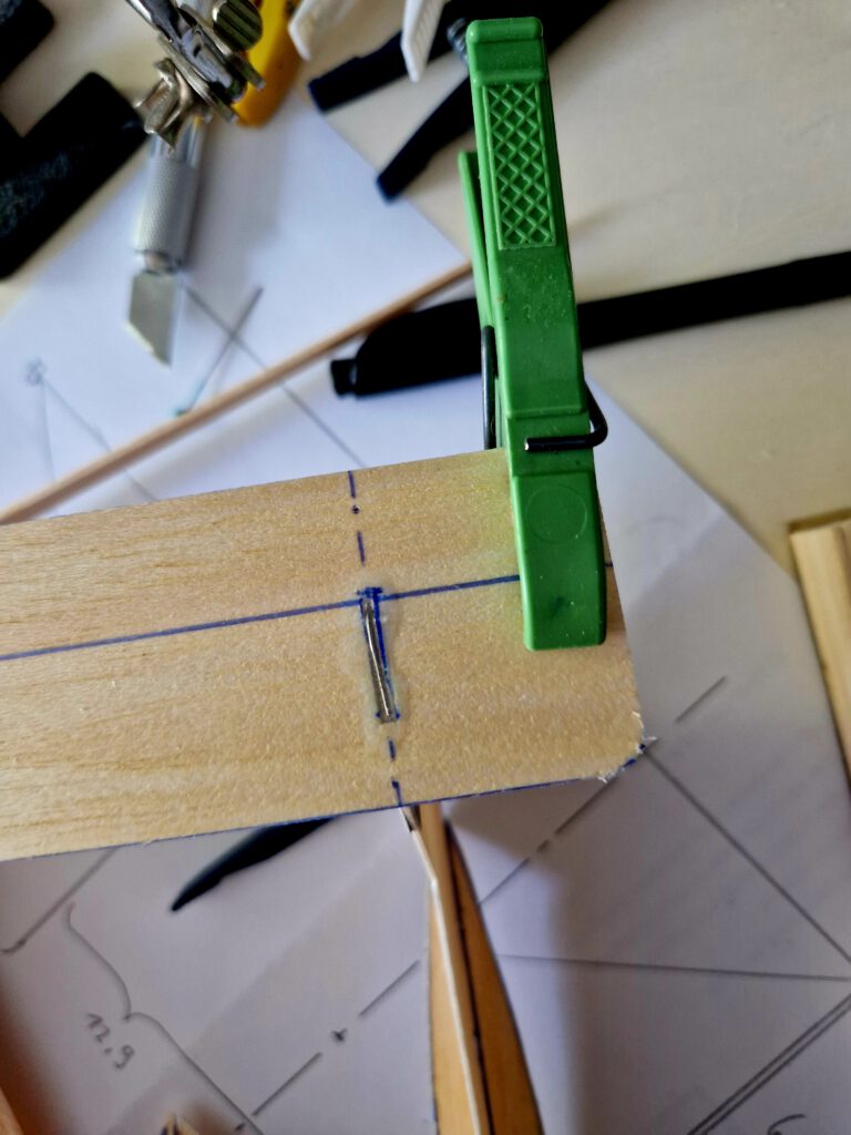
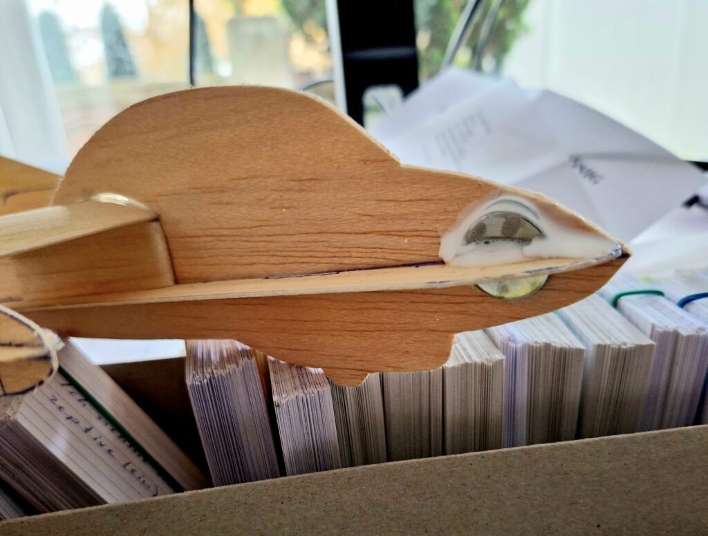
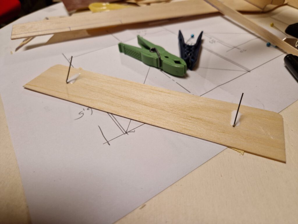
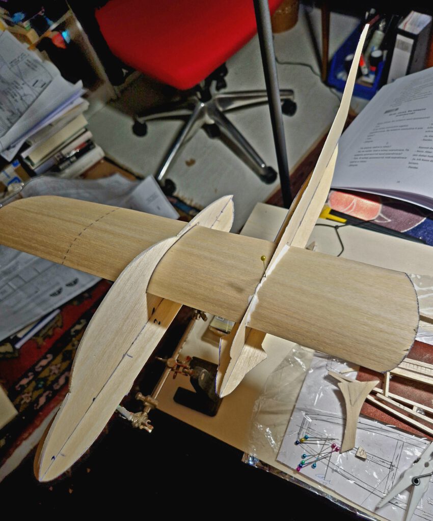
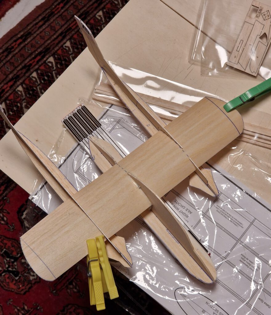
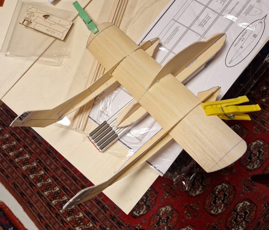
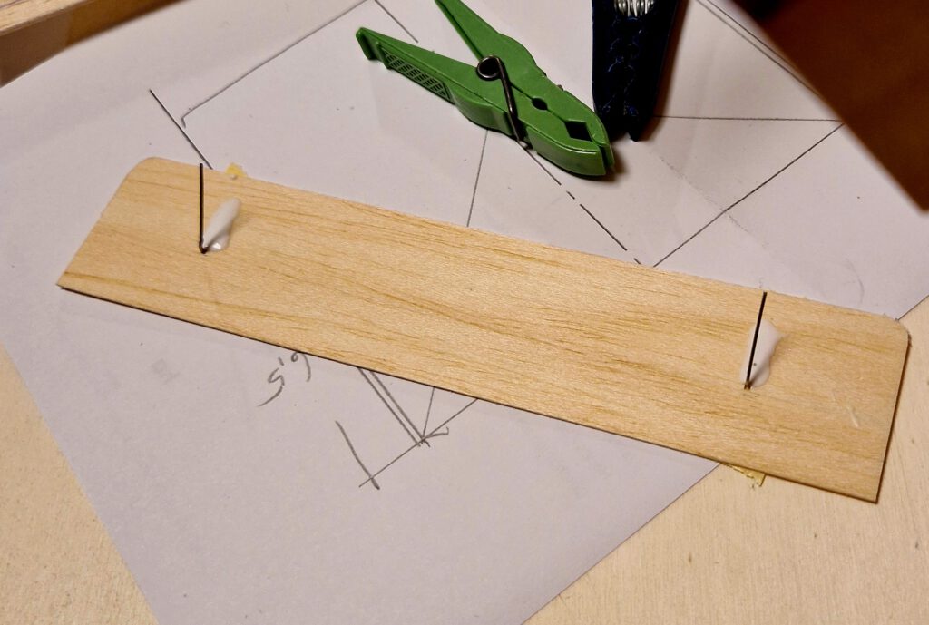
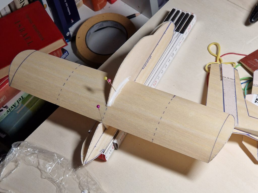
Fix fuselage gondola on your building board with needles. Cement side stiffener at 90 ° angle on right side of fuselage gondola (photo). Let dry. Repeat procedure on left side. Let dry. Cement wing supports in to their place on both sides of fuselage gondola (photo) using clamps or clothespins.
Mark positions of booms on wing with pencil. Now cement wing into fuselage gondola slot and let dry (photos).
Booms:
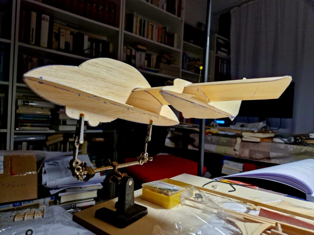
Cement first one boom on wing (photo), remember to check and measure regularly as obtaining symmetry should be your first and only aim at this step (photo). Now repeat procedure with second boom. Use so called „Third hand“ to facilitate building process (see photos).
Empennage:
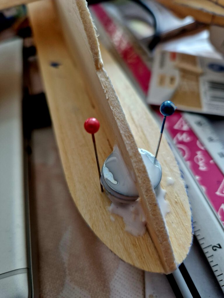
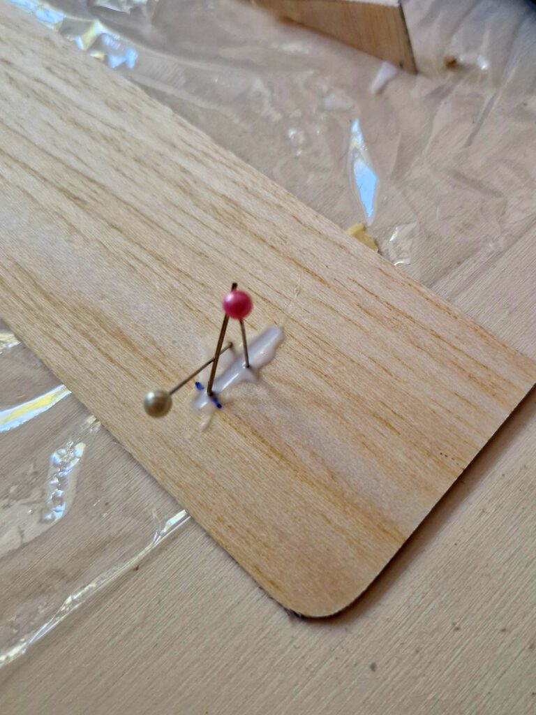
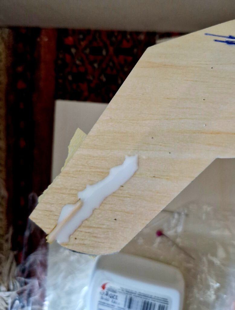
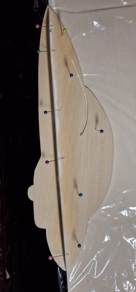
Cut slots into horizontal stabilizer. Underlay slot area on upper side of horizontal stabilizer with adhesive tape. Now turn this part upside down. Fill slot with ample amount of glue (photo). Put bent paperclip into this glue fixing it in place with needles if necessary (photo). Let thoroughly dry, then remove adhesive tape.
Final Assembly:
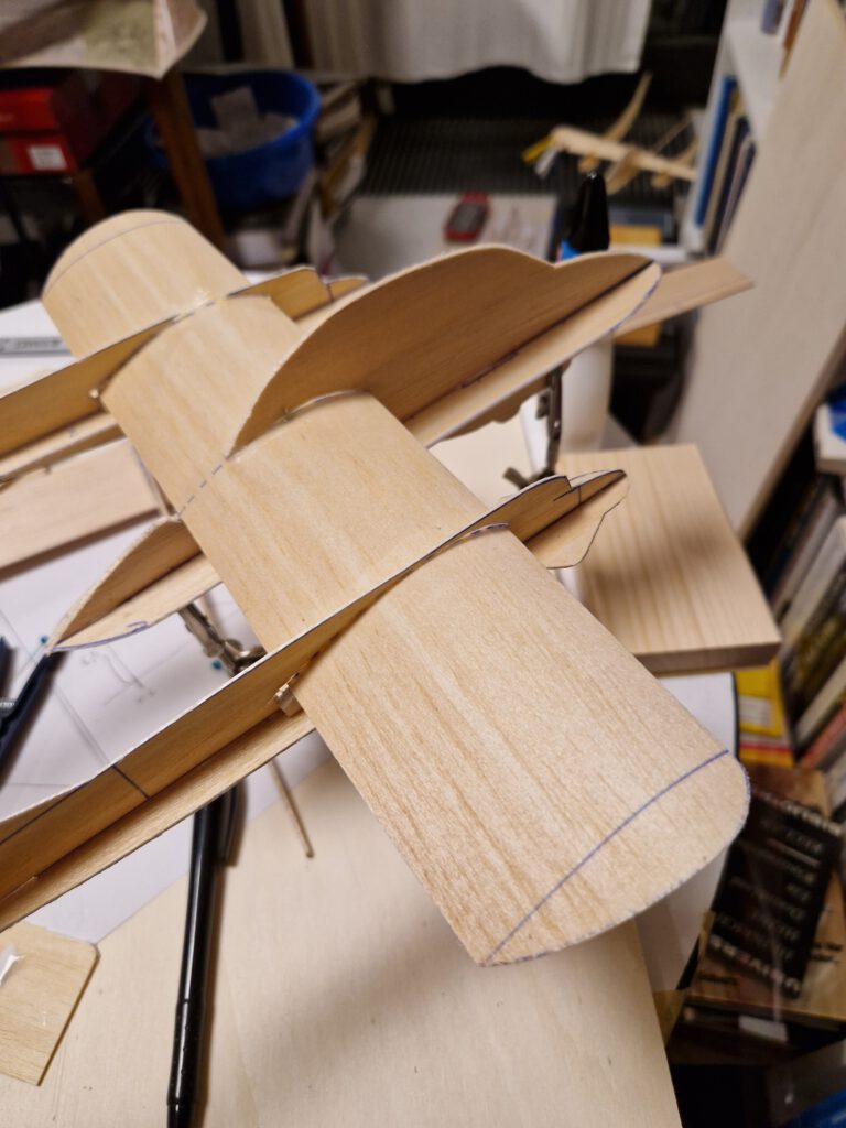
Cut out four pieces of copy paper in accordance with the outlines of the upper parts of the fins. Cement them on both sides of the slot area of each boom-fin. Keep slots cement free as they will harbor the protruding parts of the bent paperclips on the horizontal stabilizer. Cement horizontal stabilizer into its place (photo). Alternatively a small paper tube can be inserted and cemented in to the fin tips to support the horizontal stabilizer (photo).
Balance model in accordance to the given CG on plan (photo).
Tenha voos agradáveis! (ugodne letove!)
PS: I liked my Charger chuck glider that much, that I built a second slightly enlarged (span 40 cm / 16 in) version of it. If demand should show up I will draw a plan. So tell me. Thanks.

Leave a Reply