
Span 52.5 cm / 20.5 in
Weight 57 g / 2 oz
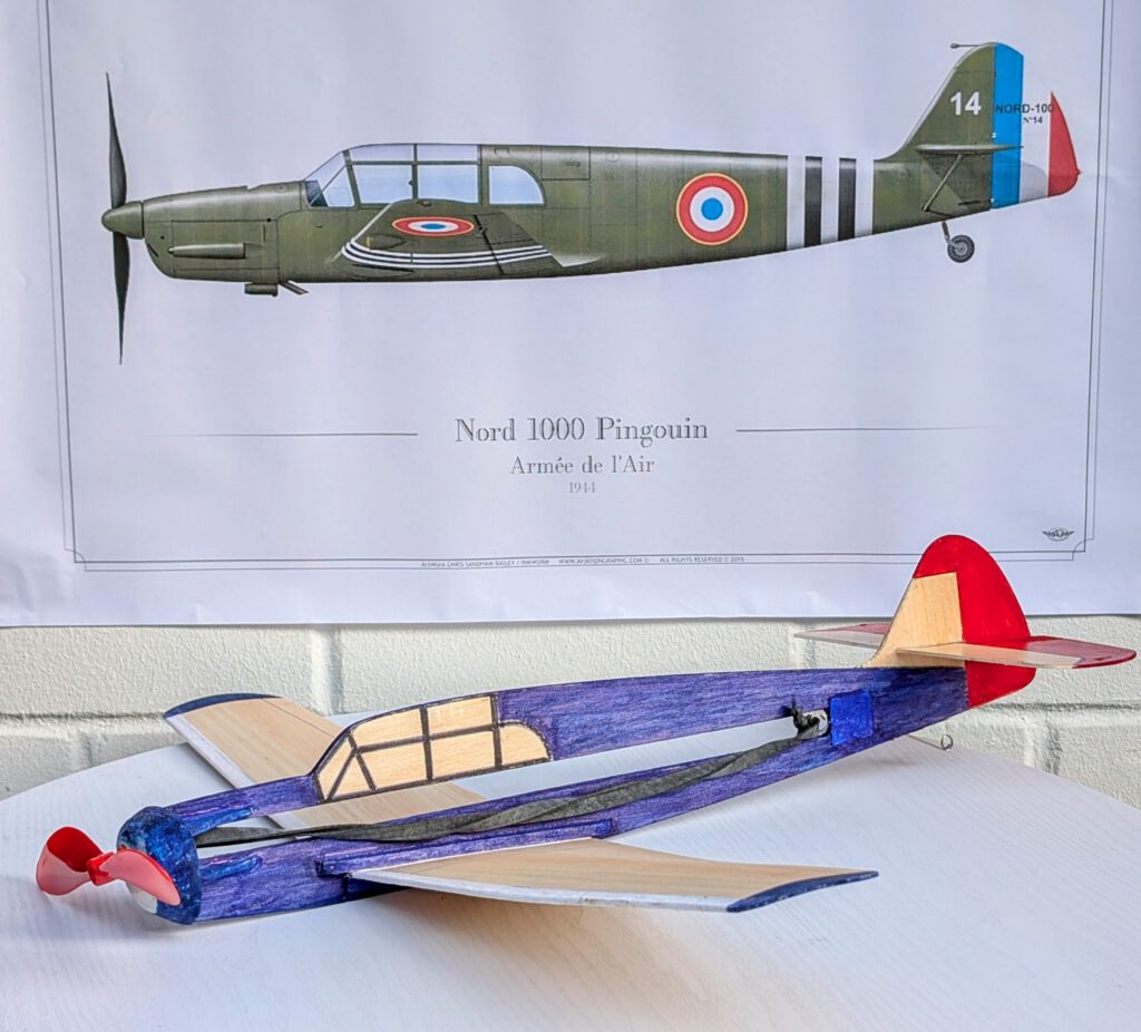
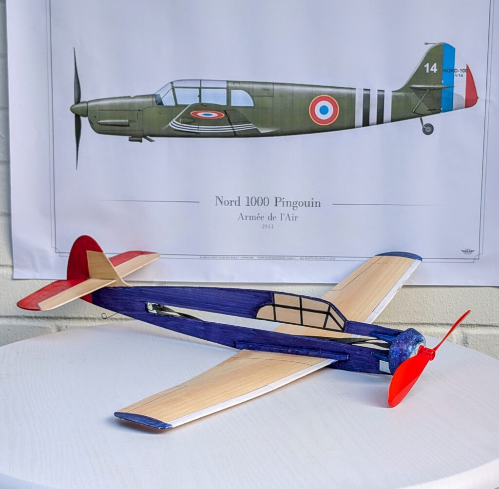
The sports and touring aircraft Nord 1000 Pingouin was a licence version of the German Mess. Bf-108 produced by French state-owned SNCAN manufacturer from 1944 until after the end of World War II. It was at the begin equipped with a German Argus As 10C piston engine later to be replaced by the French made Renault 6 Q-10 (240 hp). The Pingouin’s wingspan measured 10.61 m / 34 ft 10 in, its length 8.28 m / 27 ft 2 in and gross weight was 1,356 kg / 2,987 lb. In total 286 aircraft were built. The type was further developed into the models 1001 Pingouin I, 1002 Pingouin II and Nord 1100 Noralpha.
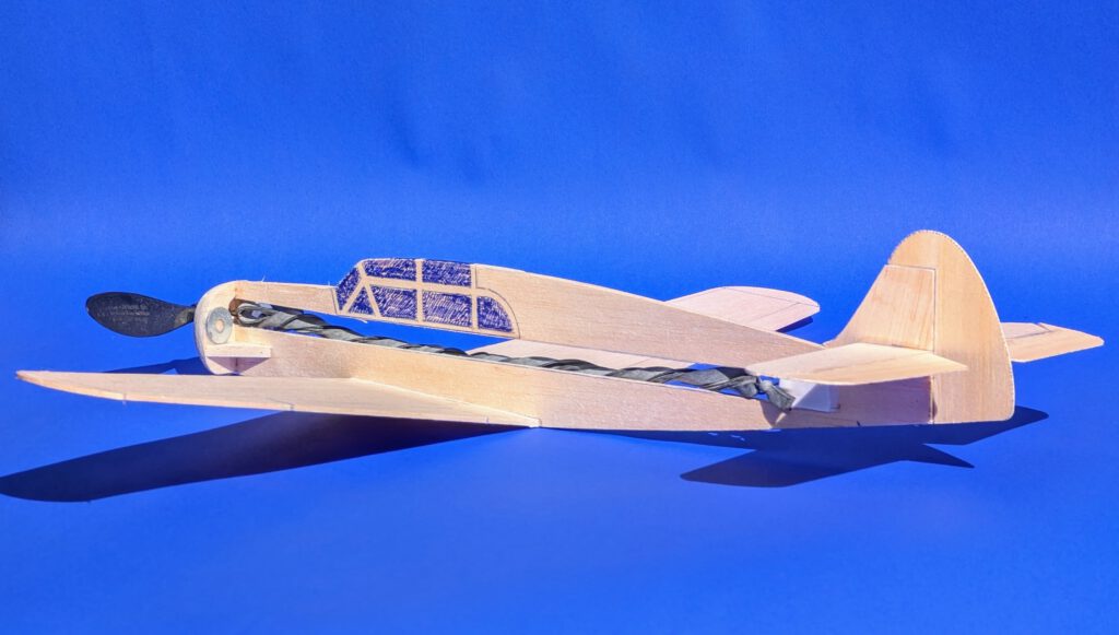
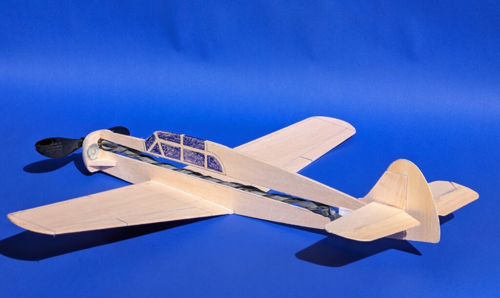

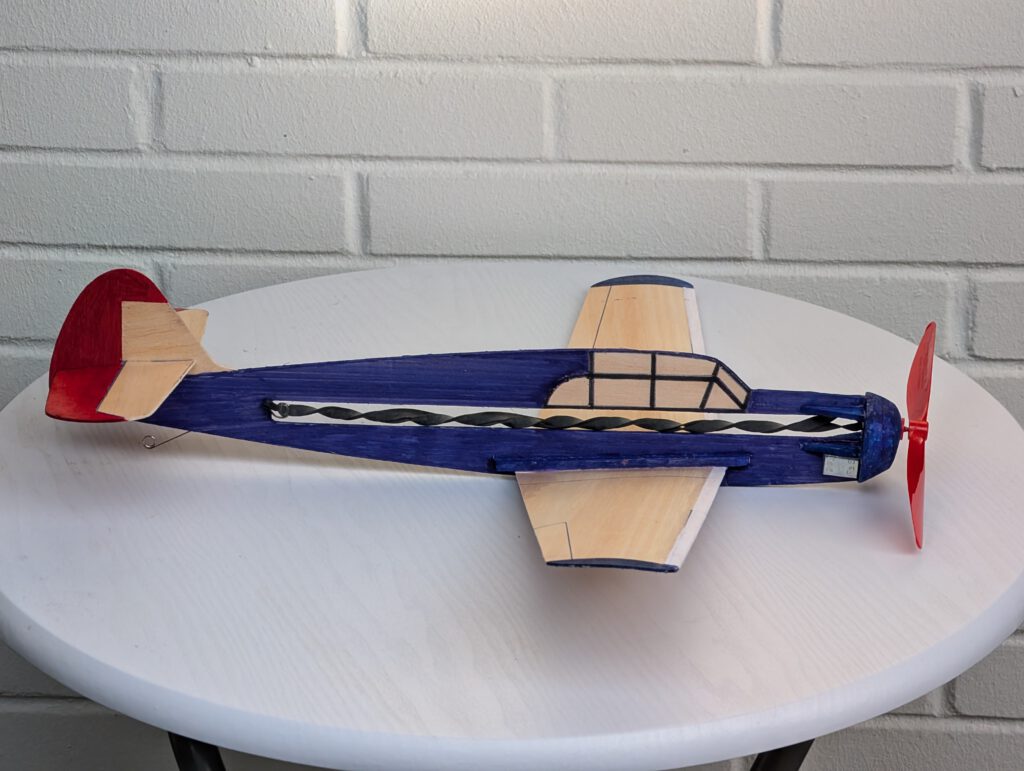
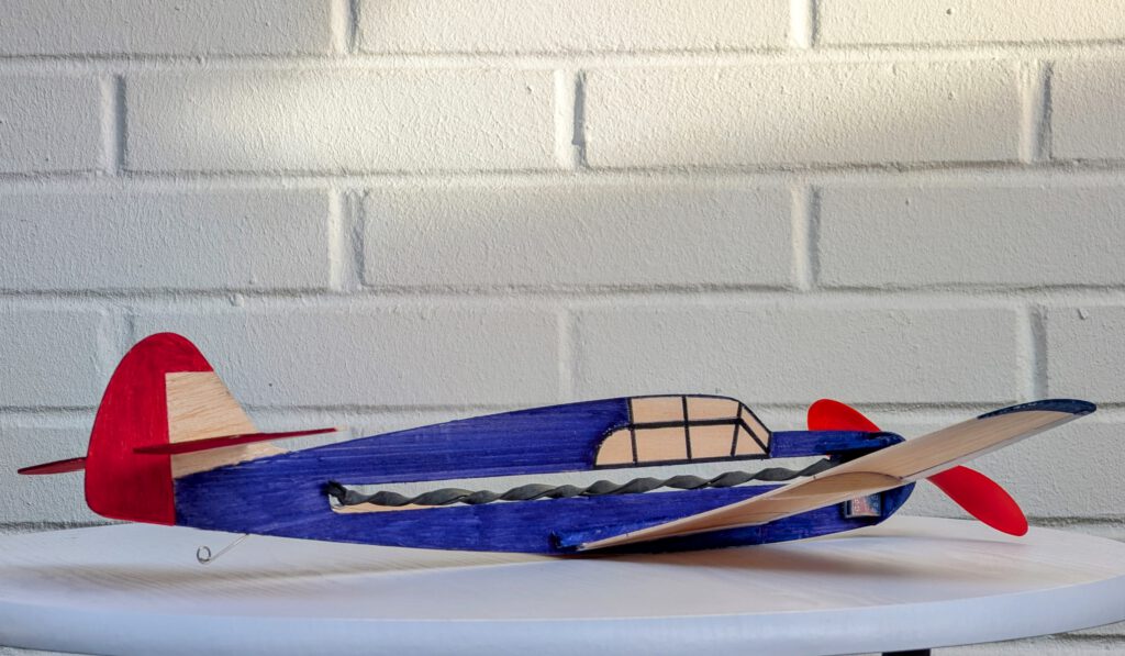
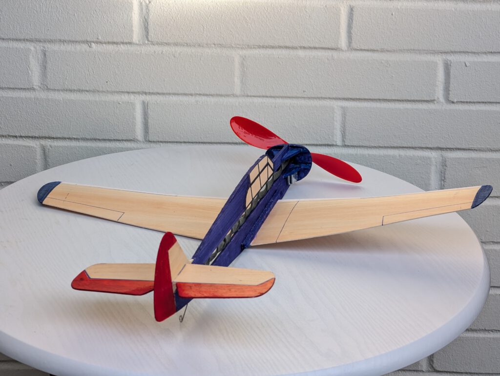
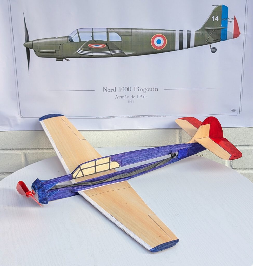
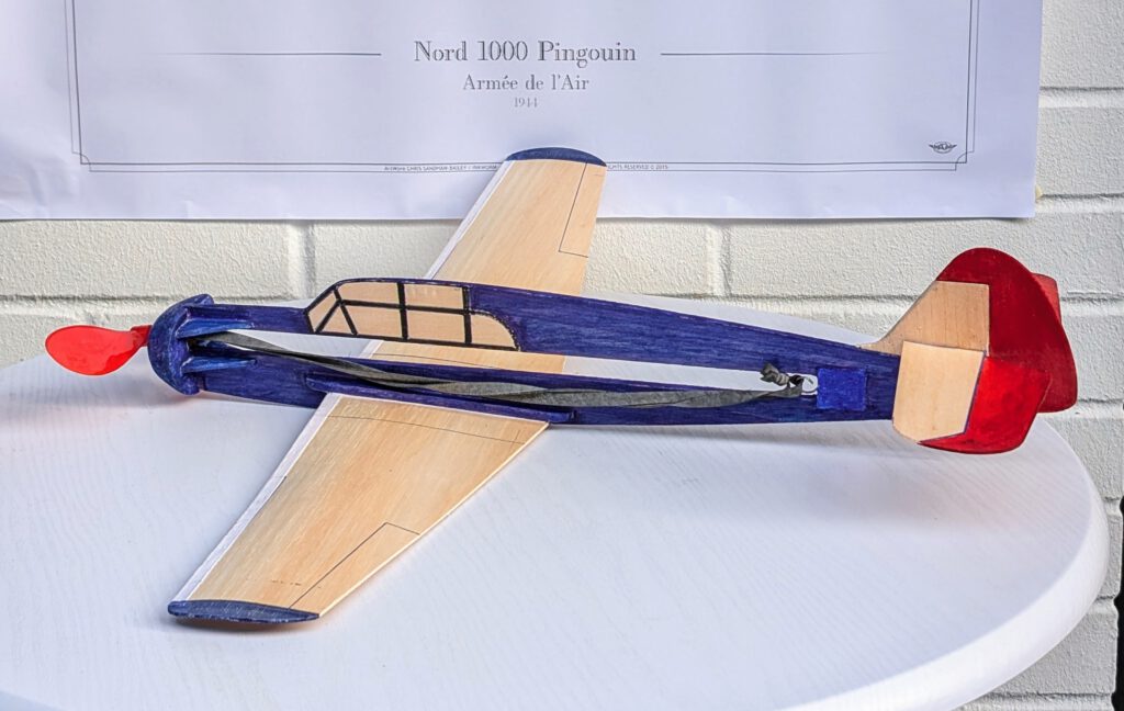
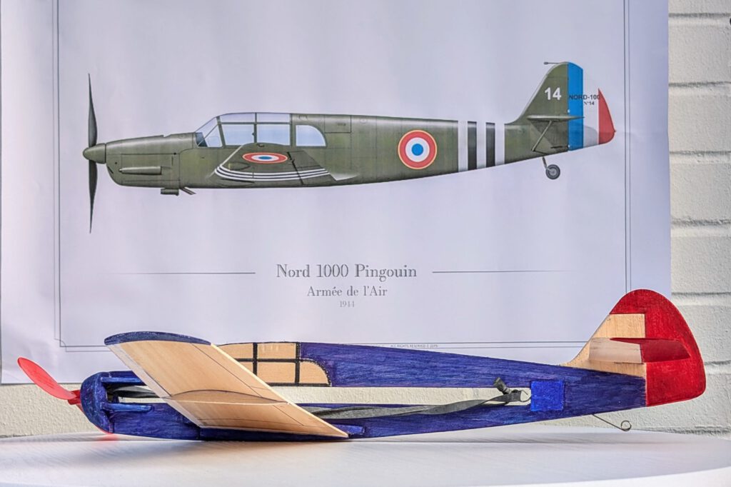
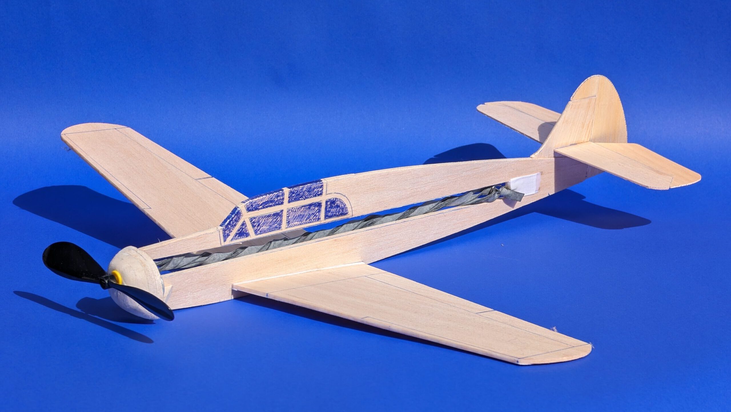
Building the rubber powered balsa profile-fuselage model Nord 1000 Pingouin.
Materials:
Fuselage: B 4; fuselage nose parts: B 5; nose stiffener triangles: B 3 or 5; rubber hook: piano wire 1.2 or 1.5 mm diameter; wings: B 1.5 or 2; horizontal stabilizer: B 1.5; elevator: B 1; vertical stabilizer: B 2; rudder: B 1; linen band width 10 mm / ½ in; ballast: 12.5 g / 0.44 oz steel or lead; one commercial airscrew 15 or better 20 cm / 6 or better 8 in diameter; rubber.
Assembly:
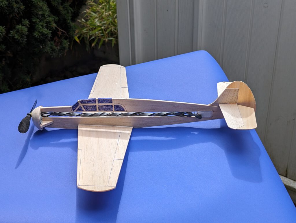
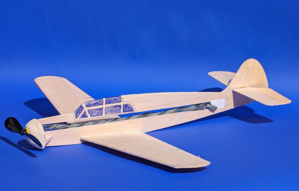
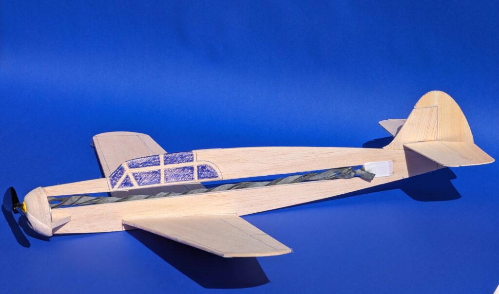
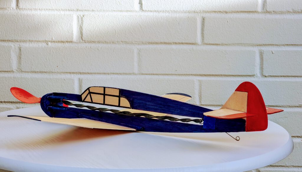
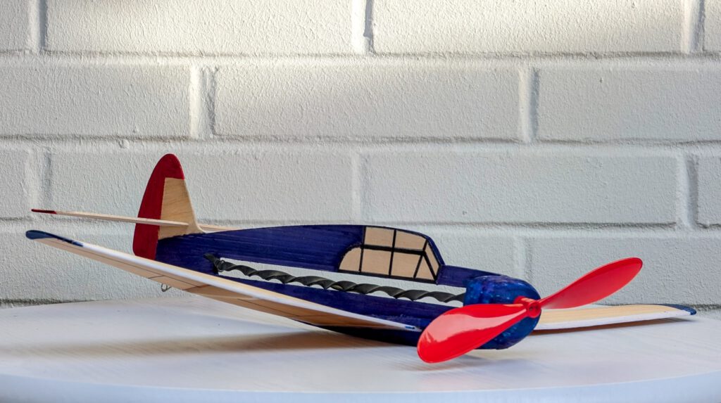
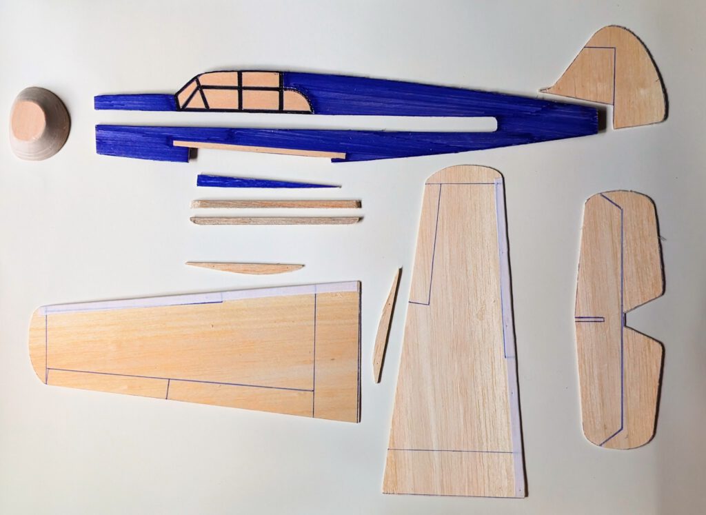
Note: Two models have been built with slight modifications (see photos).
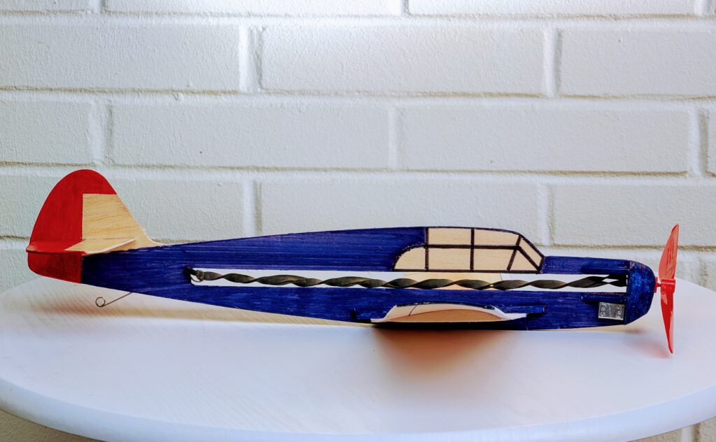
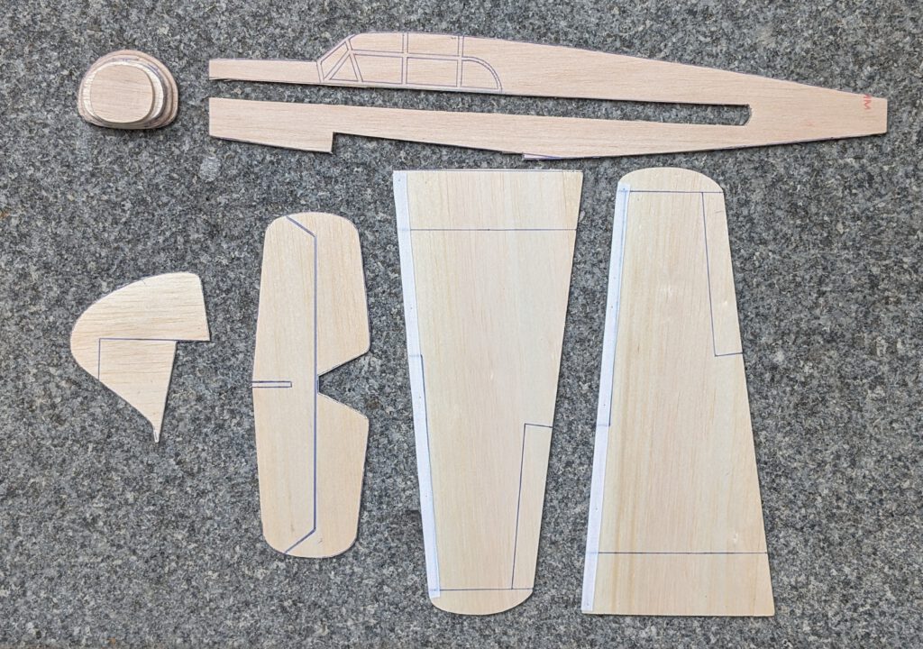
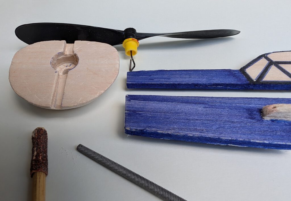
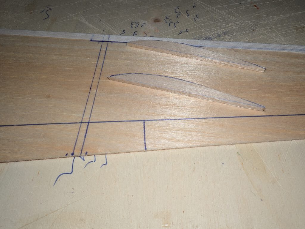
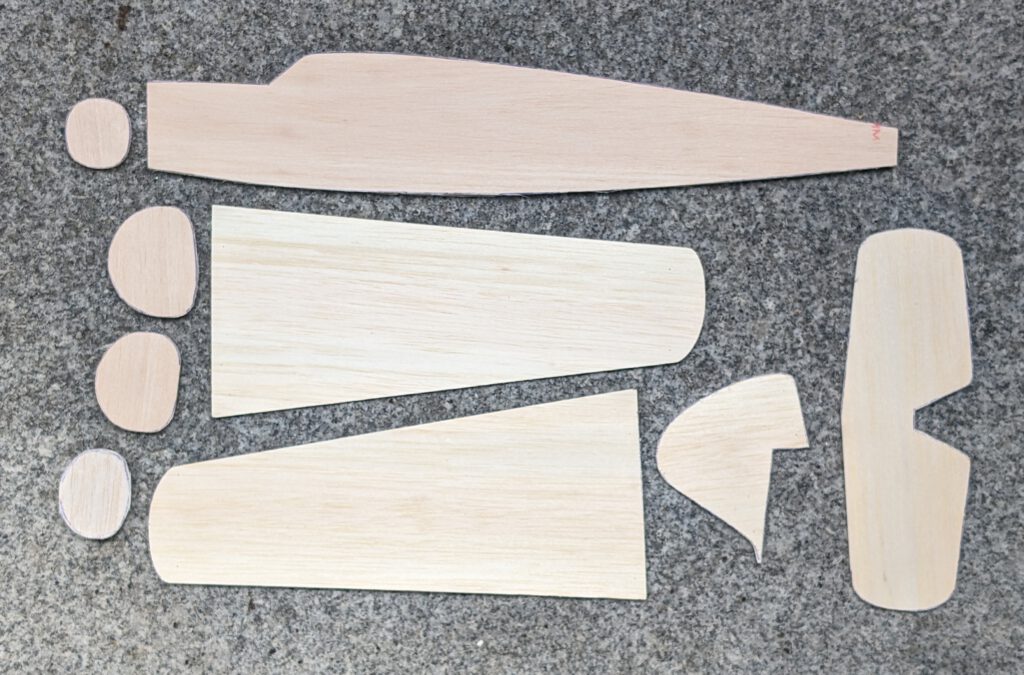
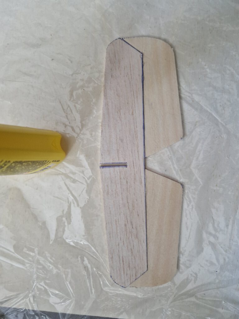
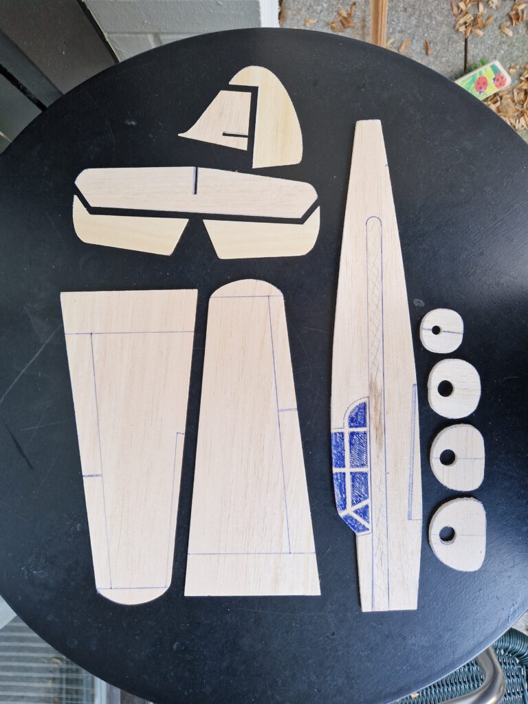
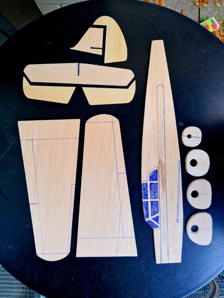
Cut out balsa parts in accordance to plan. Sand well. Transfer outlines of cockpit windows, rudders, elevators, flaps ec. from paper to wood with pen (photo).
Wing:
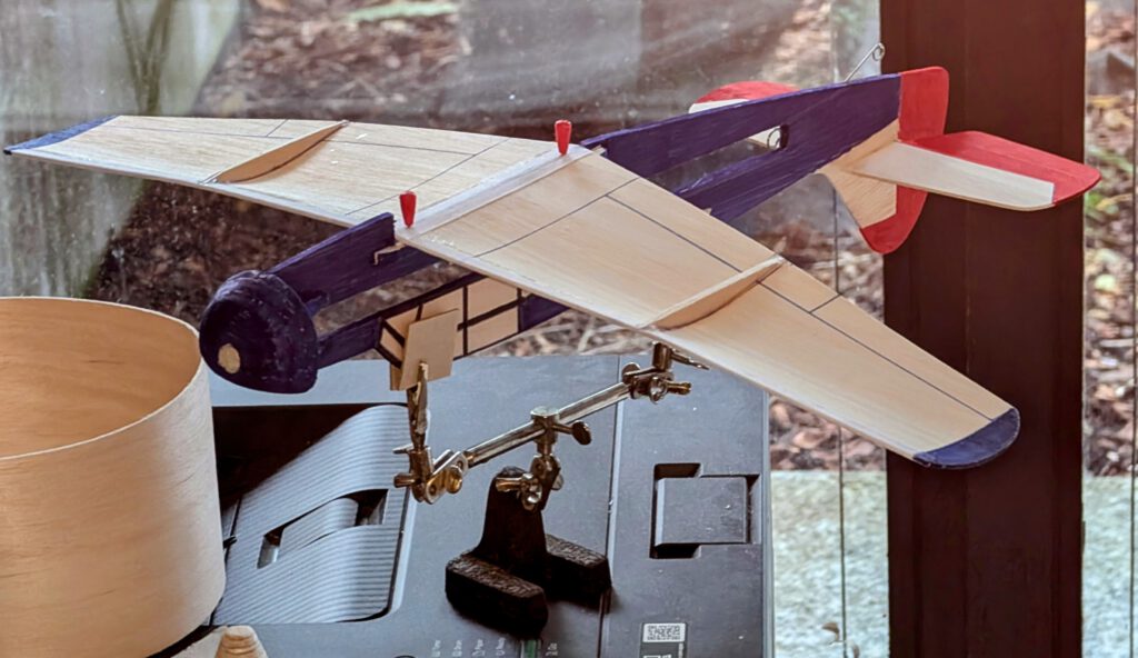
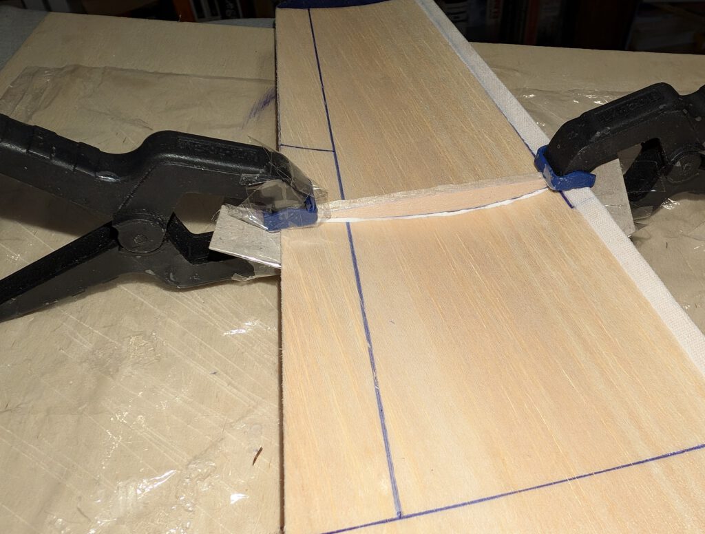
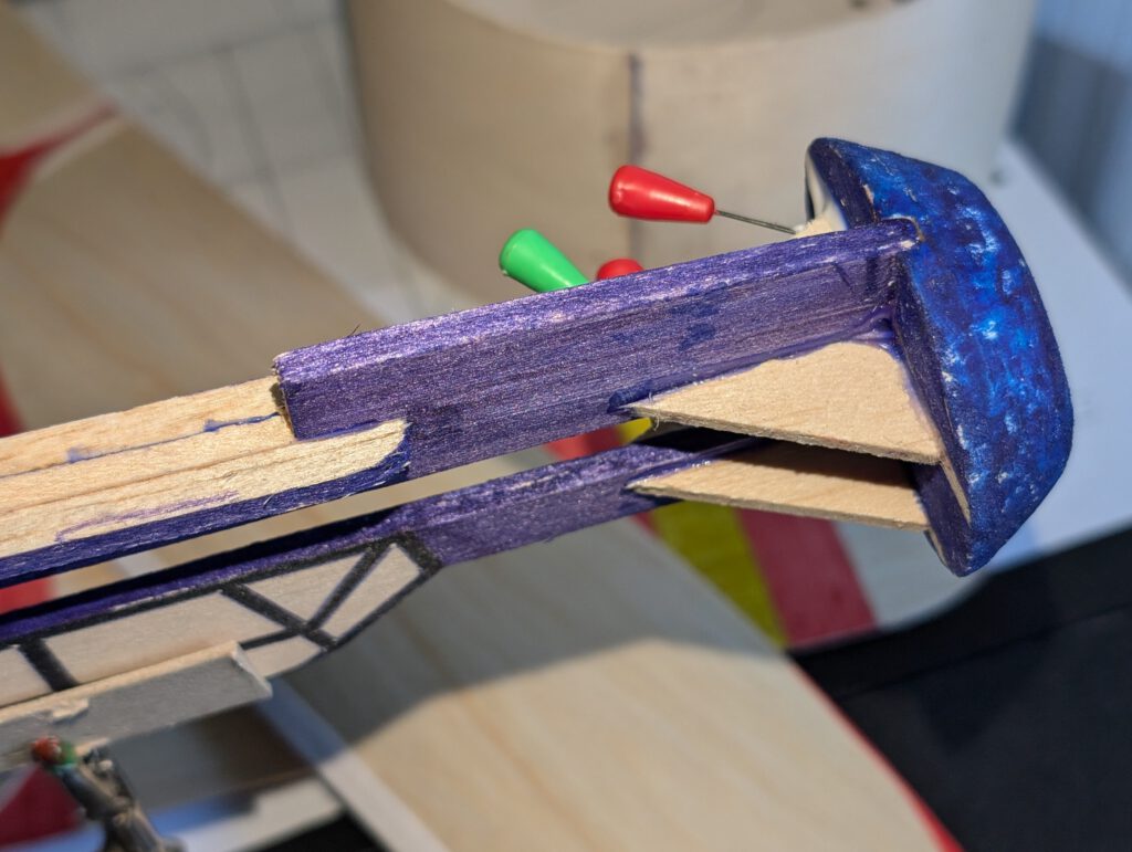
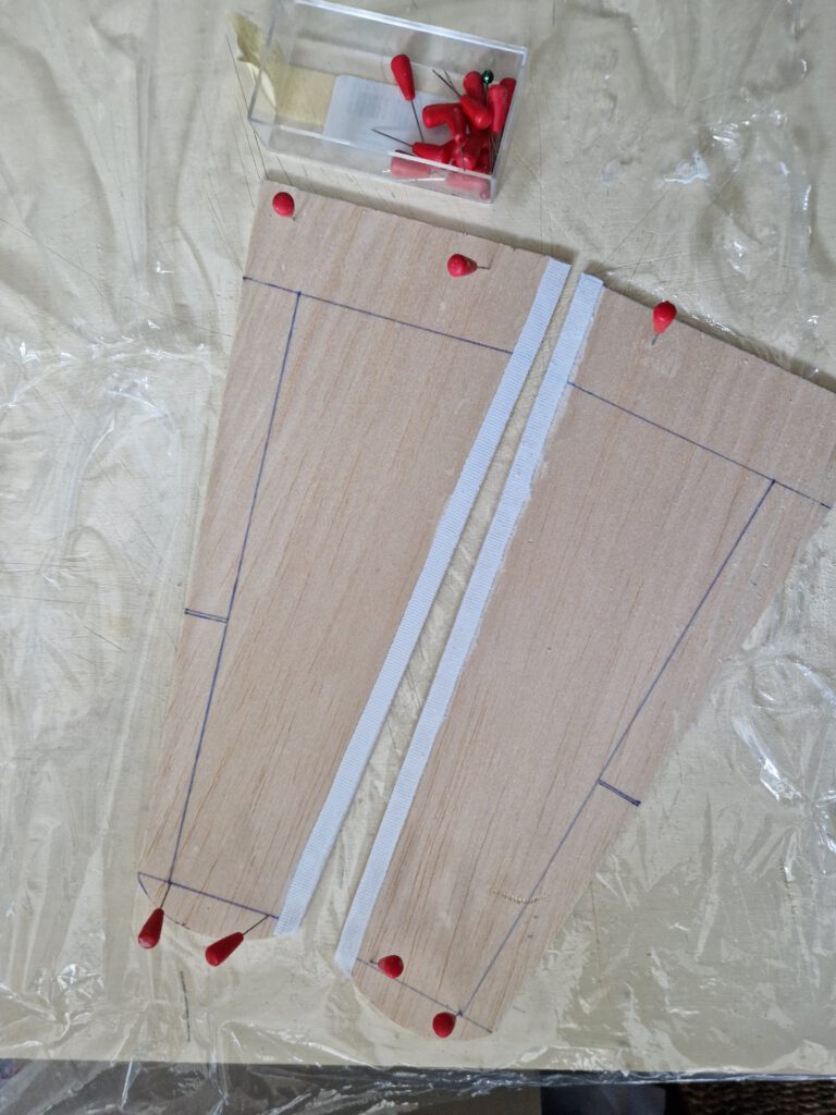
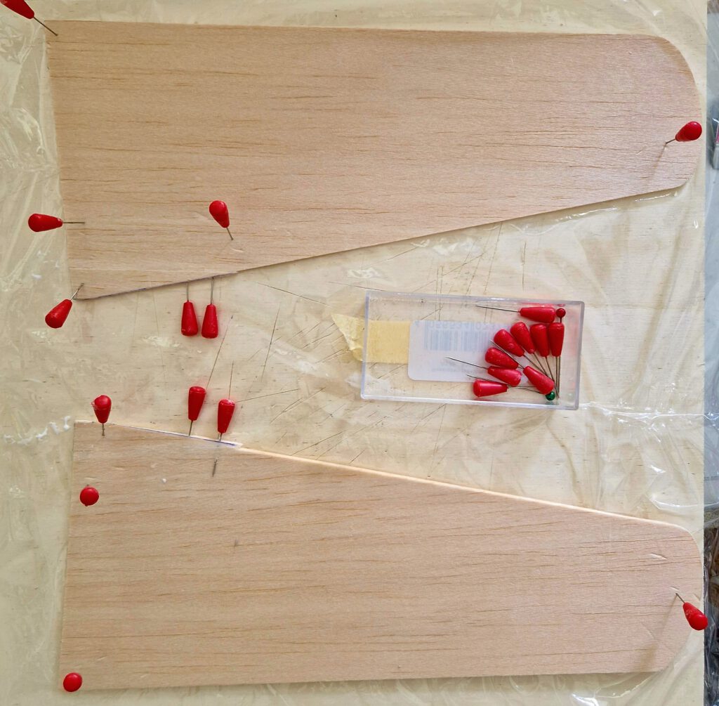
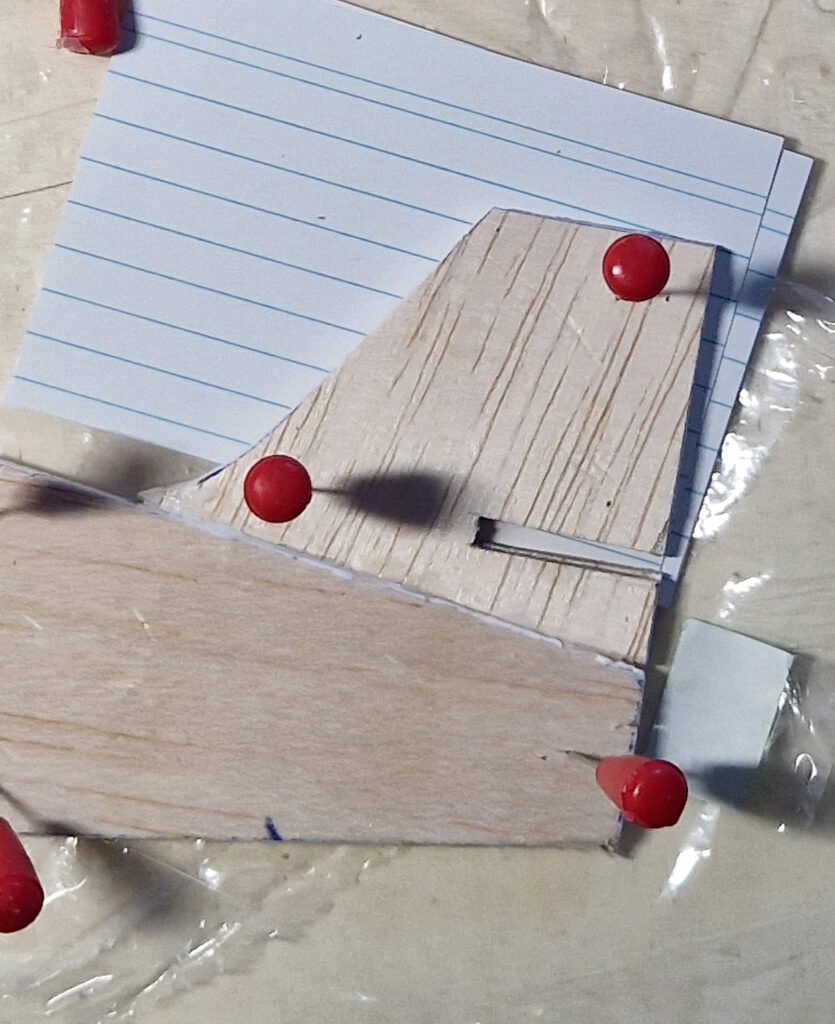
Wing consists of a right and a left wing half. As balsa sheet width is smaller than depth of wing at root add there a piece of balsa. Secure with needles (photo). Saw (if necessary) and sand contact zones.
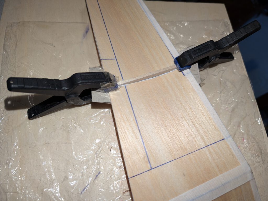
Reinforce both wing half leading edges with linen band (photo). Let dry. Fix right wing half on building board with needles. Underlay left wing half tip in accordance to required dihedral. Join both halves and cover wing center area with linen band (photo). Let dry. If wing has the tendency to rest only on one side than it is too heavy on this side. To compensate the imbalance disperse an amount of white wood glue on the opposite wing tip area. Do it if necessary twice until balance is obtained.
Fuselage:
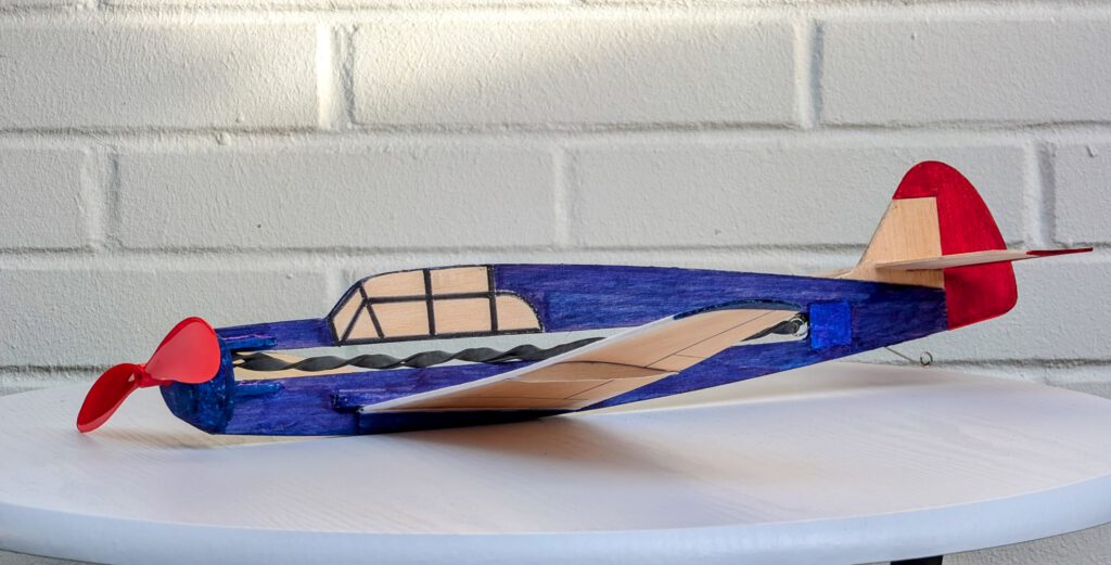
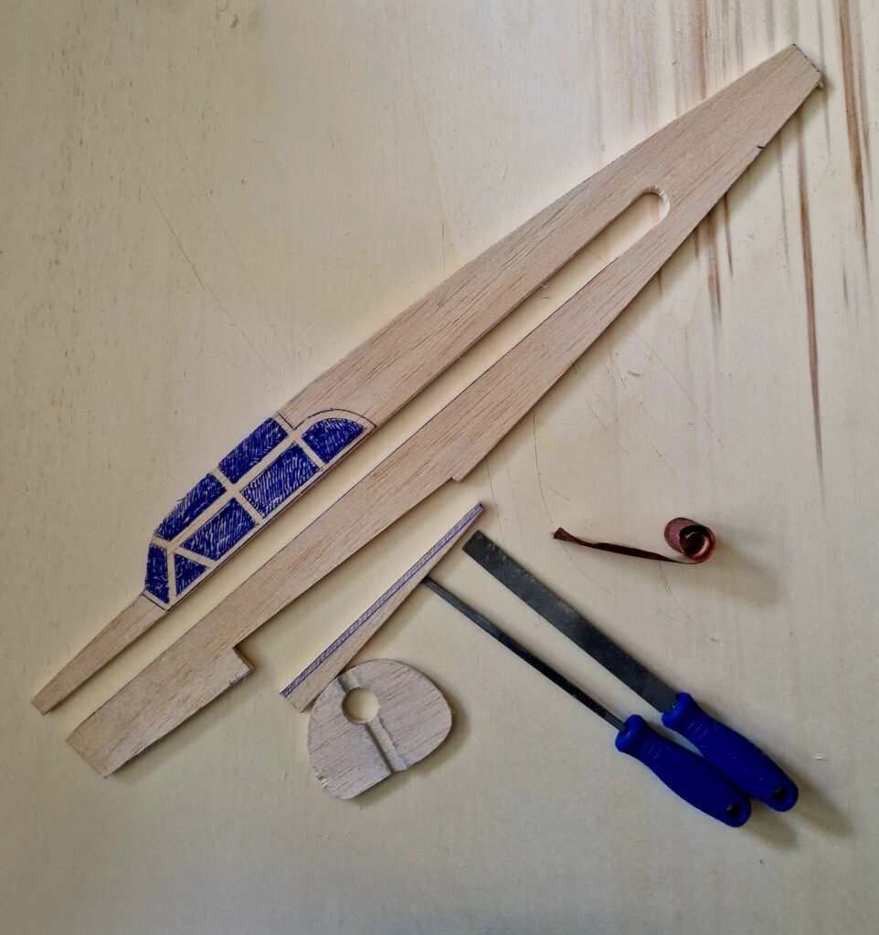
Bend as shown on plan piano wire into given hook shape. Carve out with knife and round file seat for rubber hook on left or right side of fuselage. Cement hook in place and cover hook area generously with linen band (photo). Let dry.
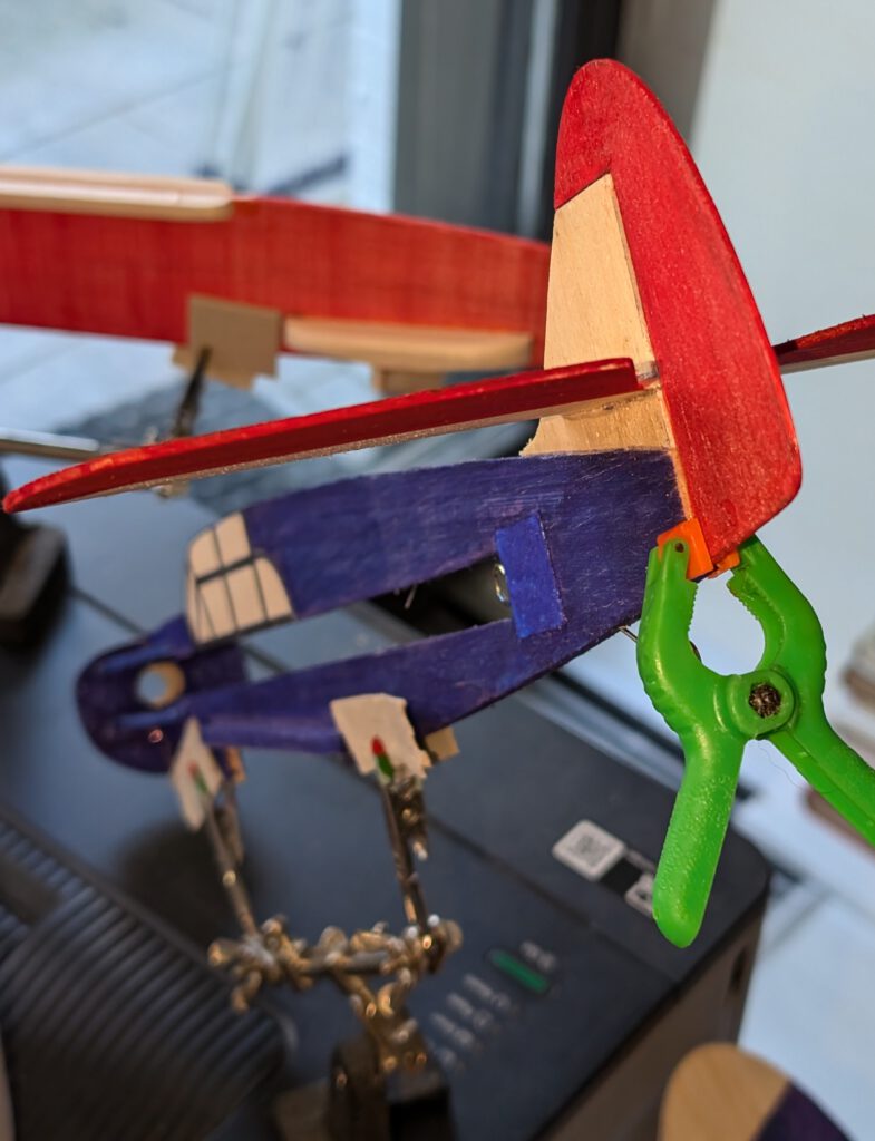
Cement vertical stabilizer on fuselage using needles to hold in place (photo).
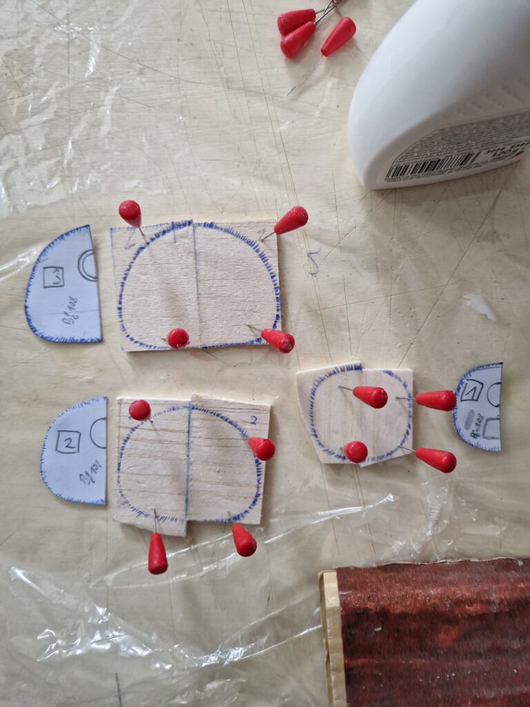
Cement B 5 nose parts one on the other as shown on plan and photo. Let dry. Sand well than treat this part with balsa putty. When dry sand again. May be this procedure has to be repeated. When the nose part is smooth you can start to carve out opening that will hold prop-bearing. Start from behind and do it not in a hurry (photo). A little electric drill machine can be useful.
Cement nose on fuselage referring to photos. When dry add nose stiffener triangles.
Empennage:
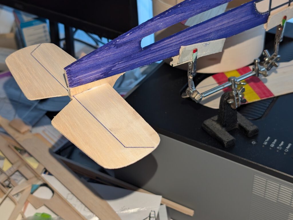
Cement elevator to horizontal stabilizer on building board. Use foam glue which allows later bending up or down the elevator a little. Let dry.
Put horizontal stabilizer into vertical stabilizer slot and cement with wood glue using needles to hold in place. Visual check symmetry from all sides. Let dry. Last part of the empennage will be the rudder. Again cement with foam glue for making it a bit movable. Use needles to hold in place. Once more visual check from all sides.
Final Assembly:
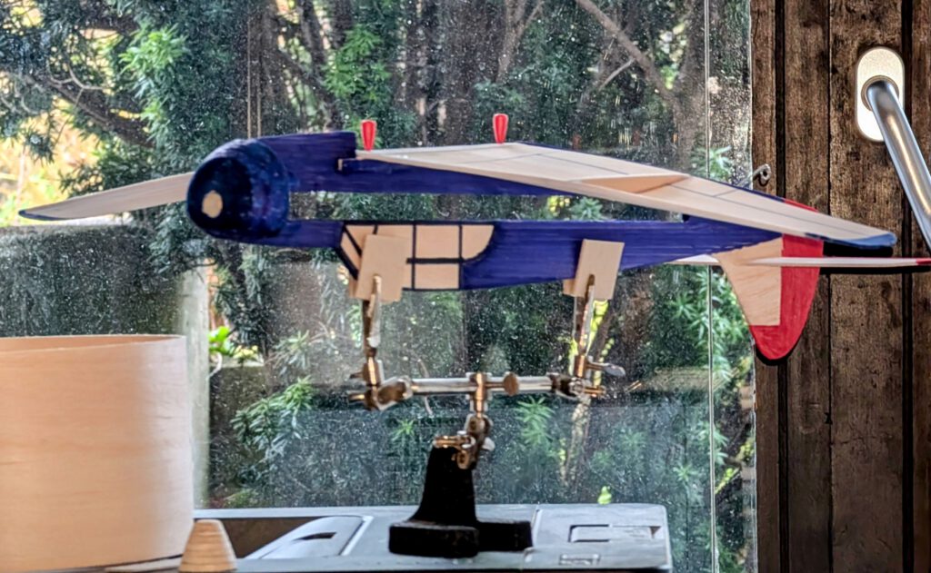
Put fuselage on a so called “third hand” upside down. Cement wing on fuselage using needles to hold in place. Doublecheck visually symmetry. Let dry.
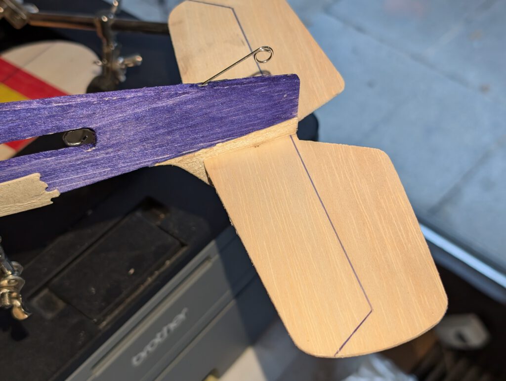
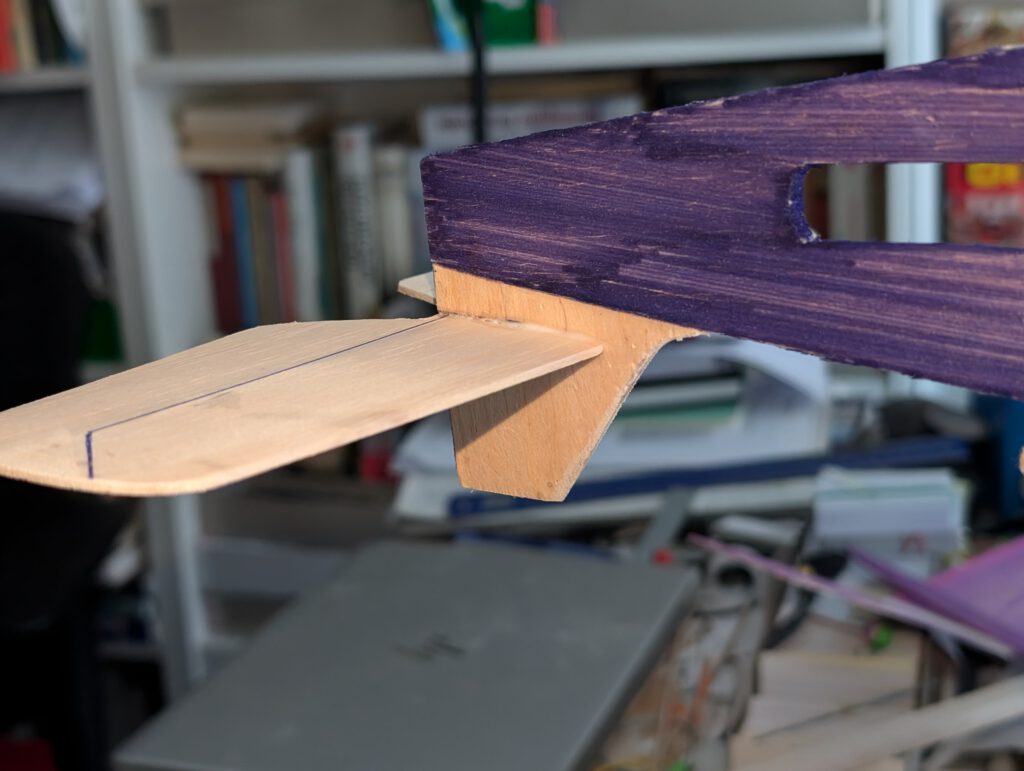
Cement underwing fuselage part in place (photo) holding it with needles in place.
Use a piece of lead or scrap metal to balance model at given position.
Remember correct center of gravity (CG) is essential for successful flights.


¡Muchos vuelos exitosos! (Multaj sukcesaj flugoj!)

Leave a Reply