
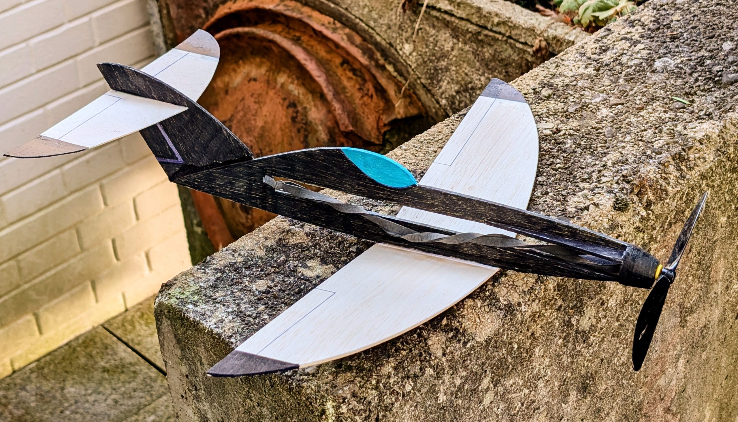
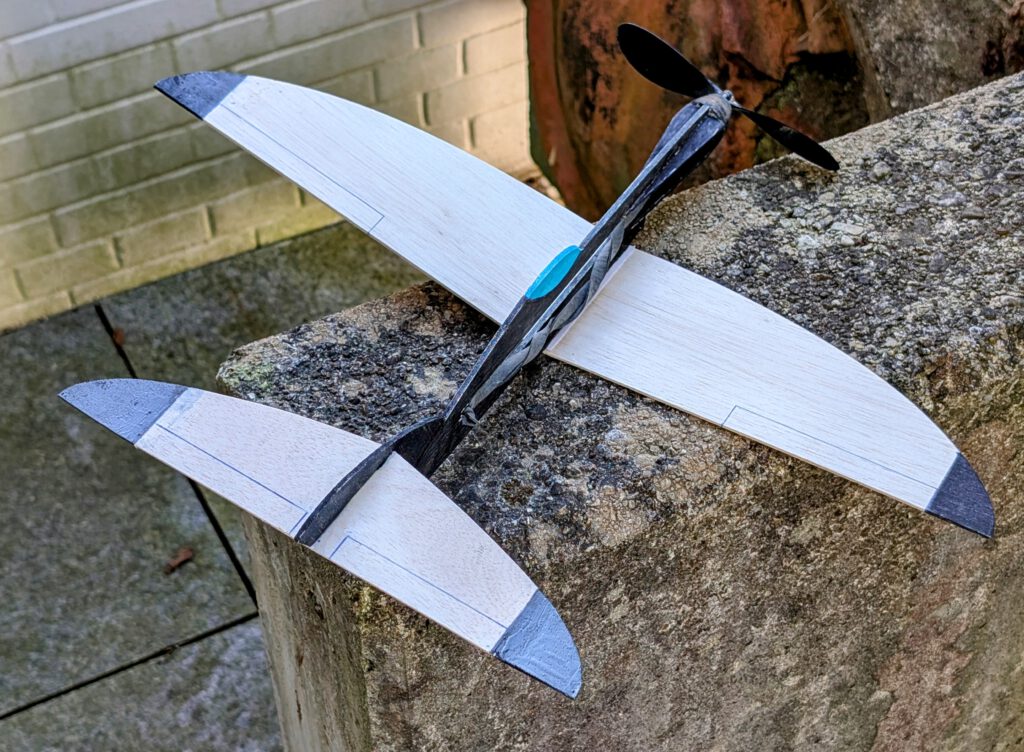
Span 48 cm / 19 in
Weight 42 g / 1.5 oz
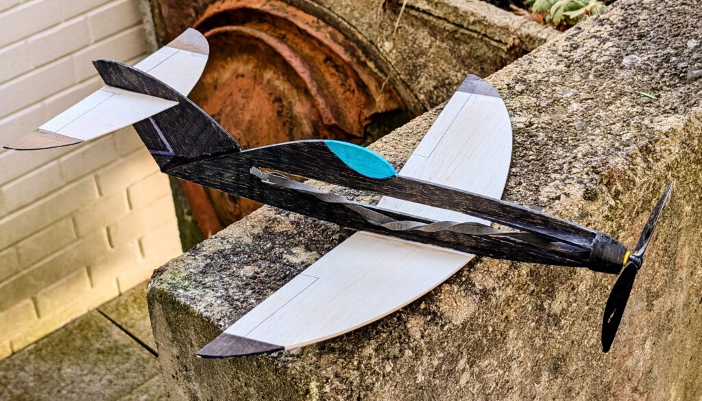
The concept:
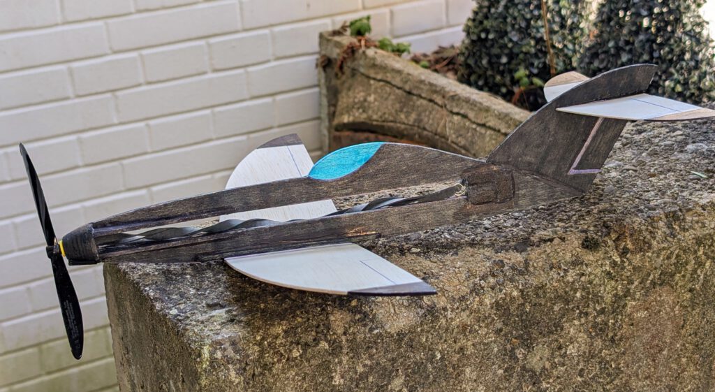
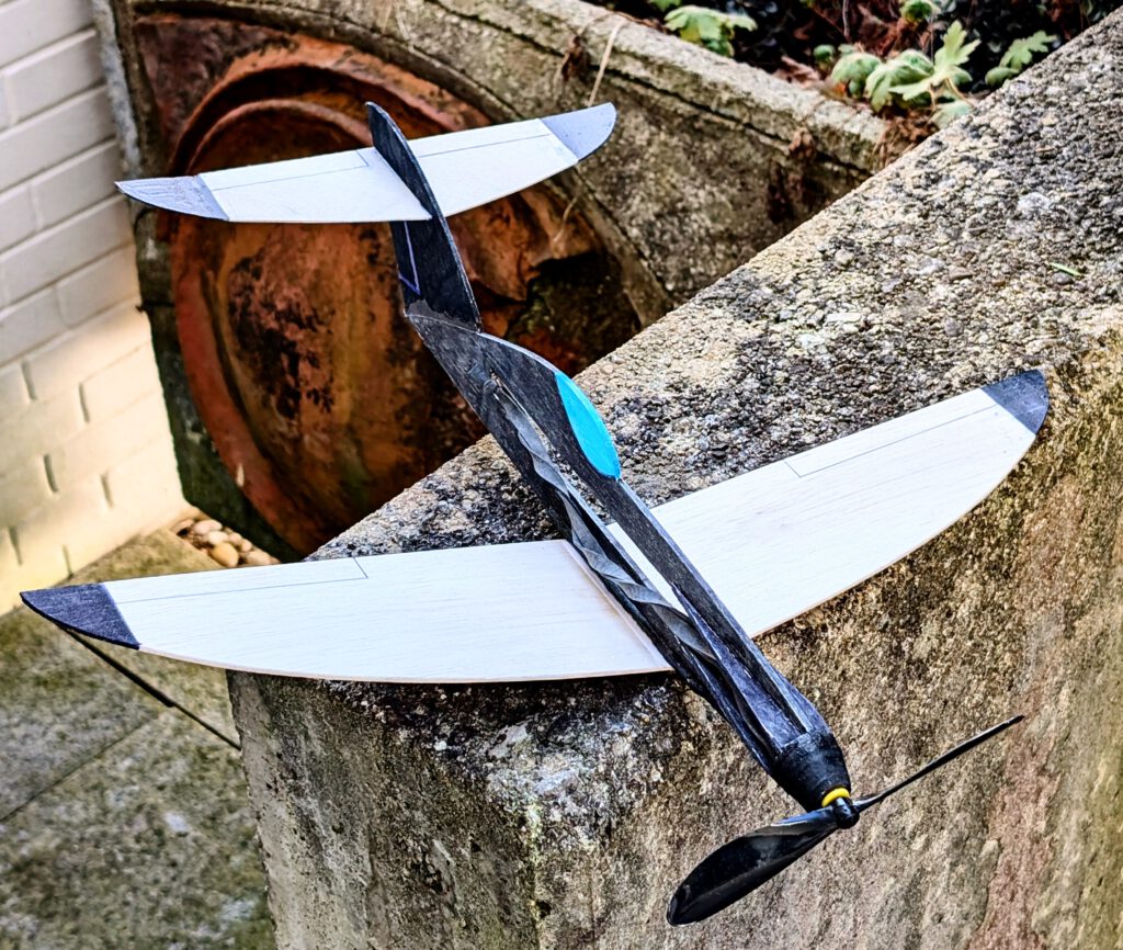
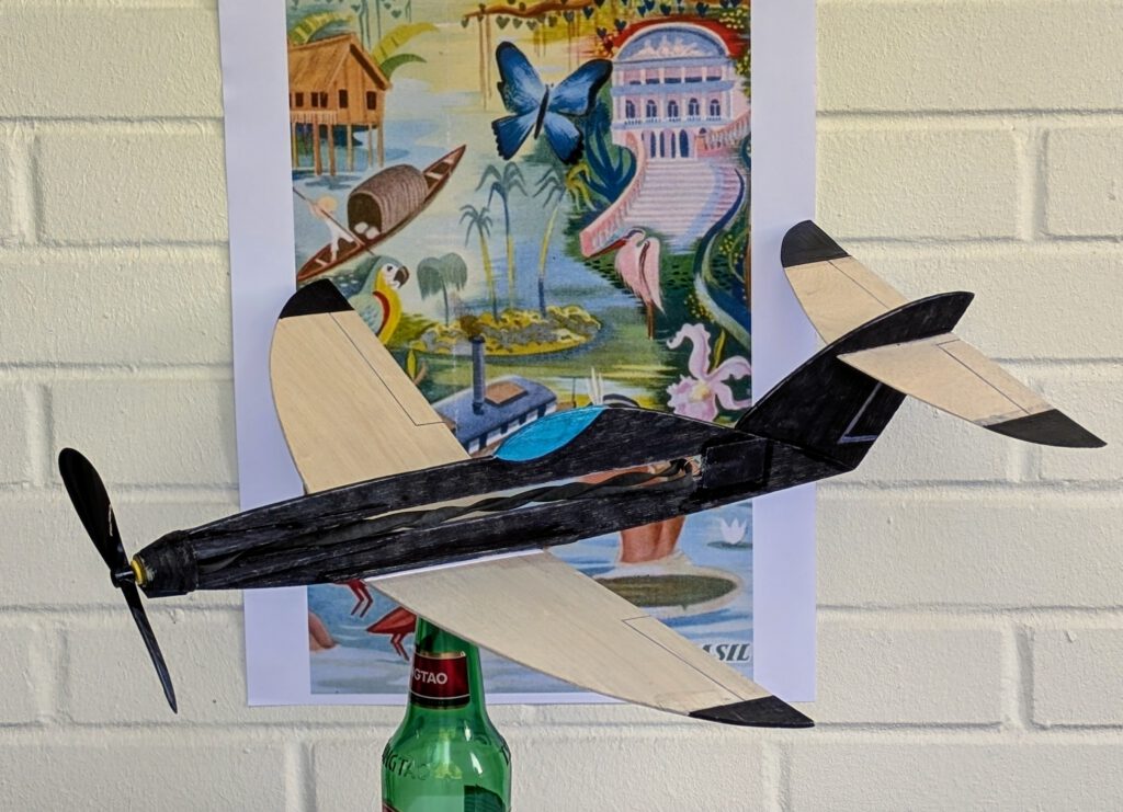
■ Shark like unique appearance
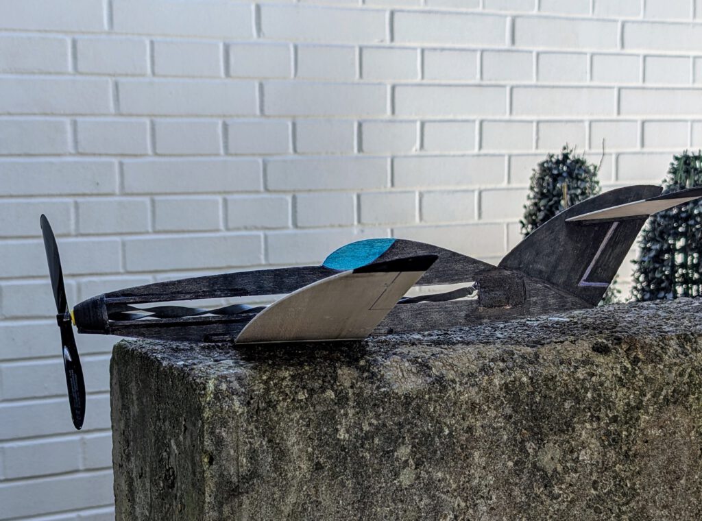
■ Low-wing monoplane
■ Intermediate size
■ Easy to build
■ Good flight characteristics
■ Few parts
■ Rubber powered
Name is Portuguese (Brazilian) and means: SHARK
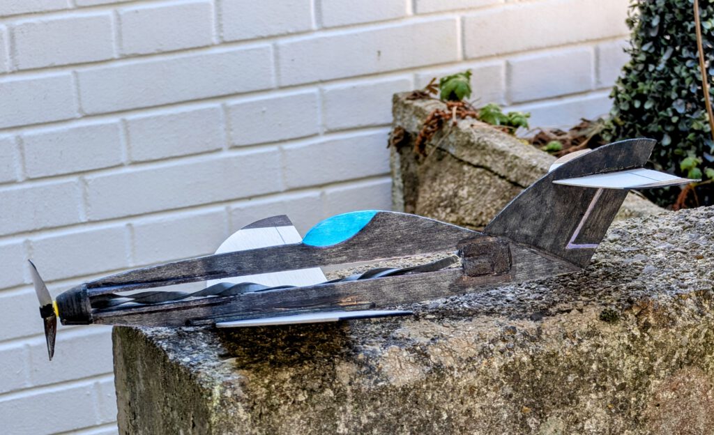
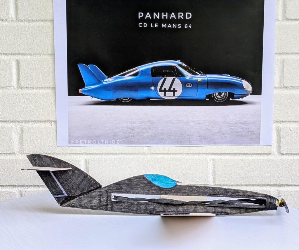
Rear end of the Tubarão was drawn up in accordance with the rear of the famous French sport coupé Panhard CD from 1963. This being probably one of the best sportcars ever considering weight, speed and miles per gallon.
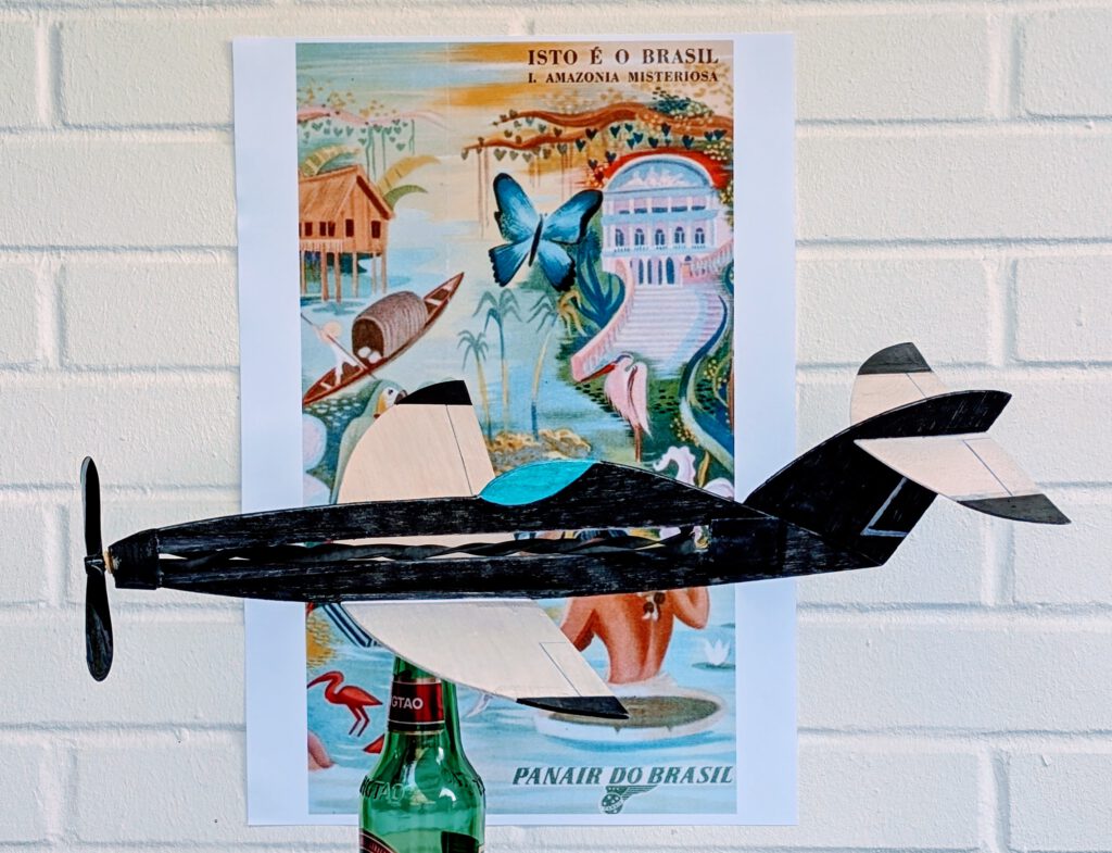
Resulting rubber powered model was a pleasing success as it led to gliders and a RPU-model, all of similar layout at different sizes and various wing configurations. See ‘Coming Soon’ section of this website for more Tubarões. (tubarão – singular, tubarões – plural)
Building the rubber powered balsa model Tubarão
Materials
Fuselage: B 3; fuselage nose parts: B 3; rubber hook: piano wire 1.2 mm diameter; wings: stiff B 1.5; wing supports: B strips 3 x 3; horizontal stabilizer: stiff B 1; horizontal stab supports: B strips 3 x 3; fin: B 1.5 or 2; linen band width 12 mm / ½ in; ballast: small piece of scrap metal or lead; one commercial airscrew 6 in diameter; blackrubber.
Assembly
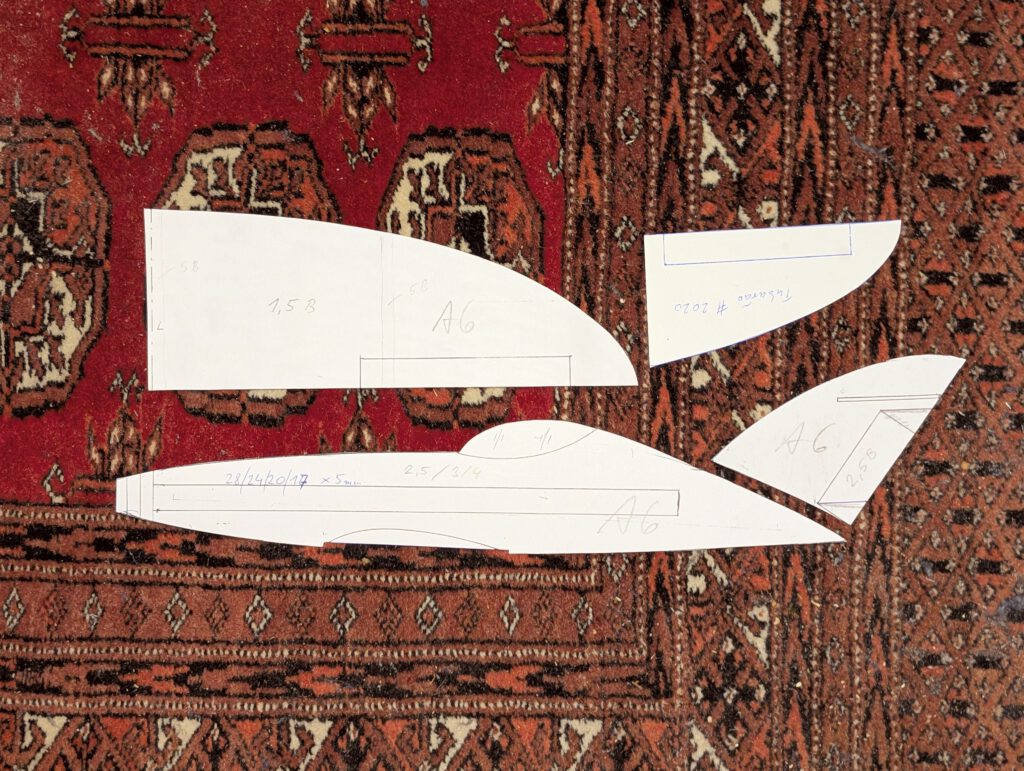
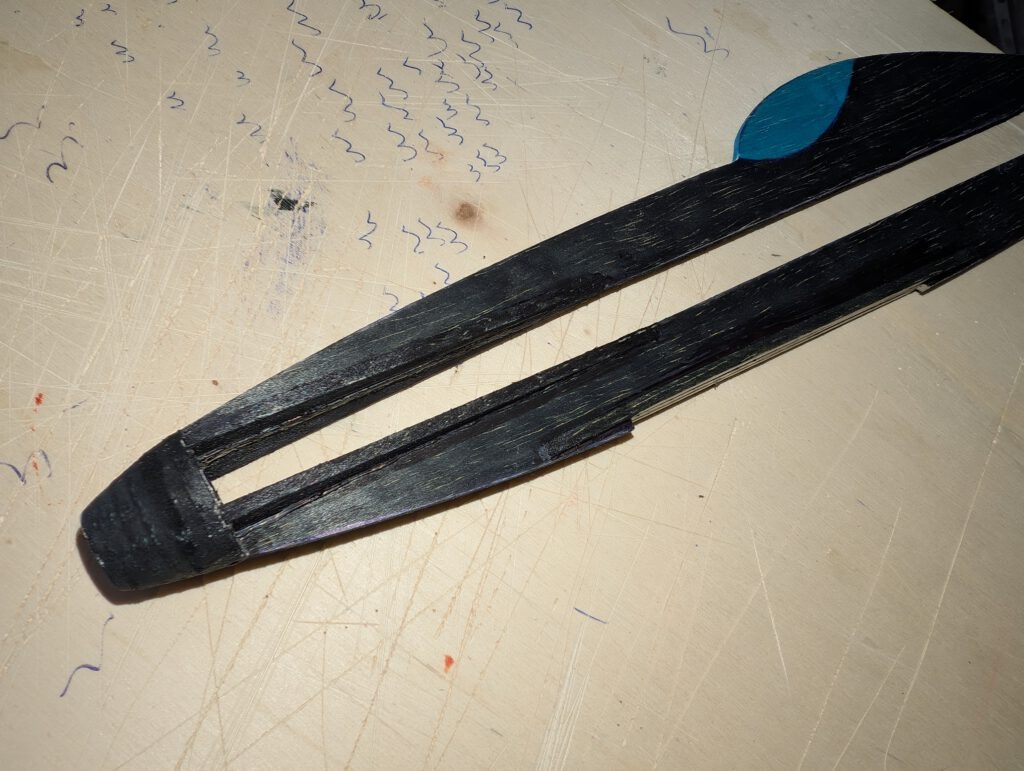
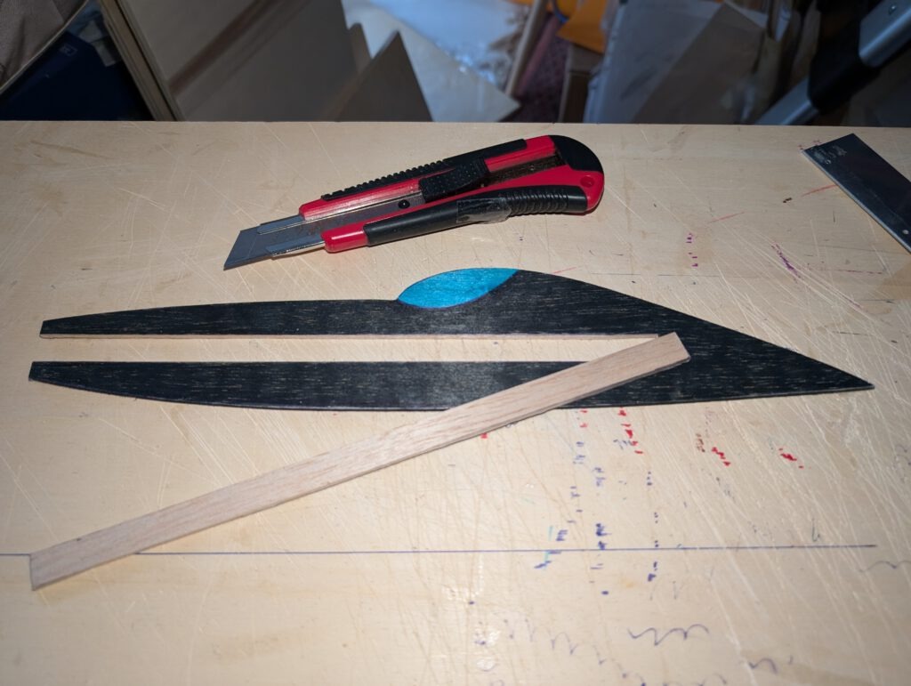
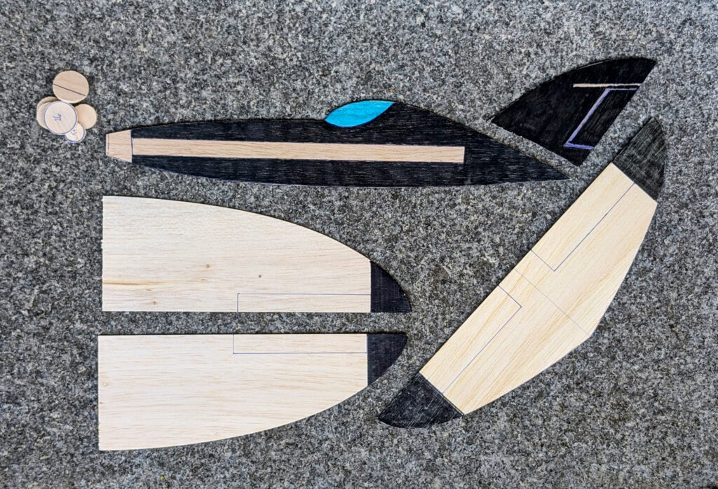
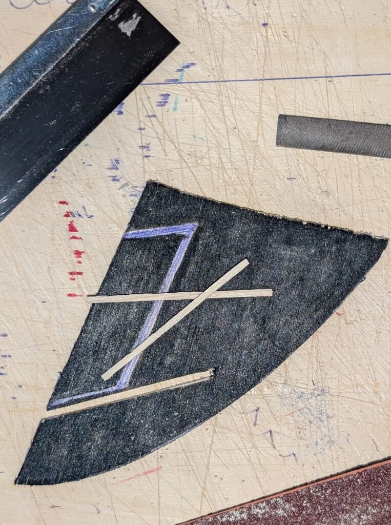
Cut out balsa parts in accordance to plan. Sand well (photo). Transfer outlines of cabin, rudders, elevators, ec. from paper to wood with pen. Cut out all necessary slots. Paint your model at this stage (photo).
Wing:
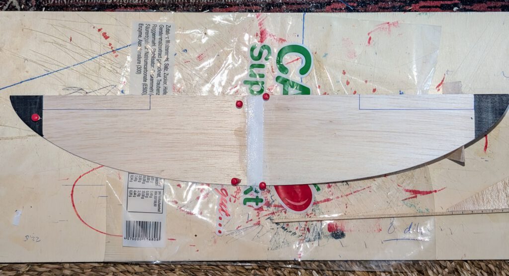
Wing consists of a right and a left wing half. Fix one half on building board with needles.Cement corresponding half by paying attention to dihedral given in plan. When dryreinforce center area with linen band (photo) and again let dry.
If wing has the tendency to rest only on one side, then it is too heavy on this side. To compensate the imbalance, disperse a small amount of white wood glue on the opposite wing tip area and let dry. Do it, if necessary, twice until balance is obtained.
Fuselage:
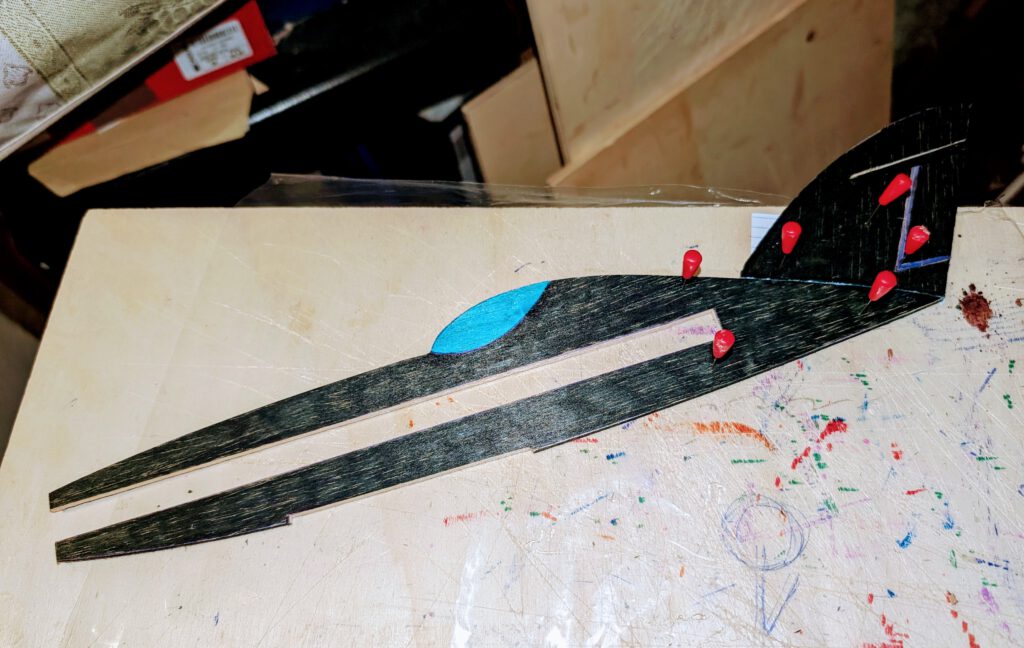
Bend as shown on plan piano wire into given hook shape. Carve out with knife and round file seat for rubber hook on left or right side of fuselage. Cement hook in place and cover hook area with linen band as seen on plan and on photos. Let dry.
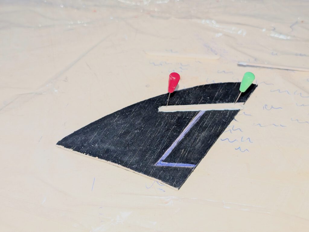
Cement fin on fuselage using needles to hold in place (photo). Always visual check twice that symmetry is obtained.
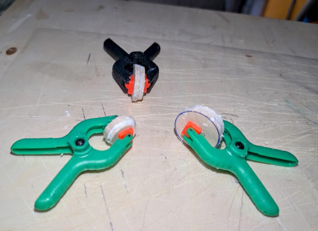
Cement wing support strips into their given places. Hold with clamps or clothespins or with needles.
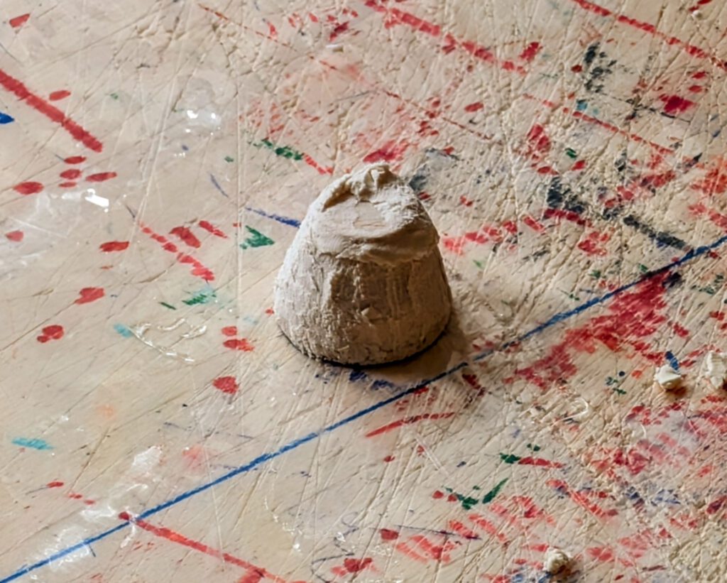
Cement circular nose parts one on the other as shown on photos and let dry. Sand well than treat this part with balsa putty (photo). When dry sand again. May be this procedure has to be repeated. When the nose part is smooth you can start to carve out opening which will later hold prop-bearing. Start from behind and don’t do it in a hurry. A little electric drill machine can be useful.
Cement nose assembly on fuselage according to photos. When dry add triangle nose stiffeners two on each side.
Empennage:
Cement horizontal stab support strips in place and let dry (photo).
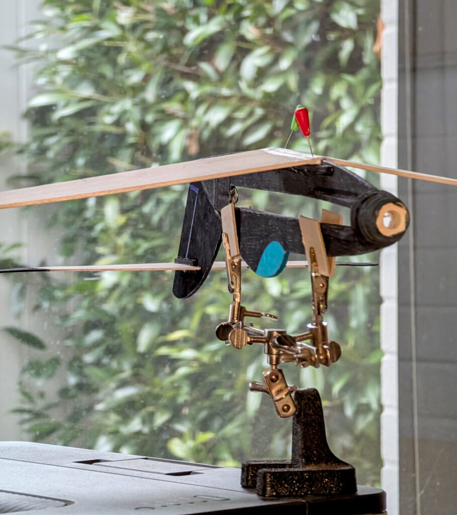
Fix fuselage on so called ‘third hand’. Cement horizontal stabilizer into its place using needles to hold. Visual check symmetry from all sides. Let dry.
Final Assembly:
Put fuselage on a ‘third hand’ upside down. Cement wing on wing supports using needles to hold in place (photo). Doublecheck visually symmetry. Let dry.
A piece of lead or scrap metal may be used to balance model if necessary.
Remember correct center of gravity (CG) is essential for successful flights.
Make your first test glides and first powered flights over tall grass.
Palju edukaid lende! (Molts vols d’èxit!)

Leave a Reply