

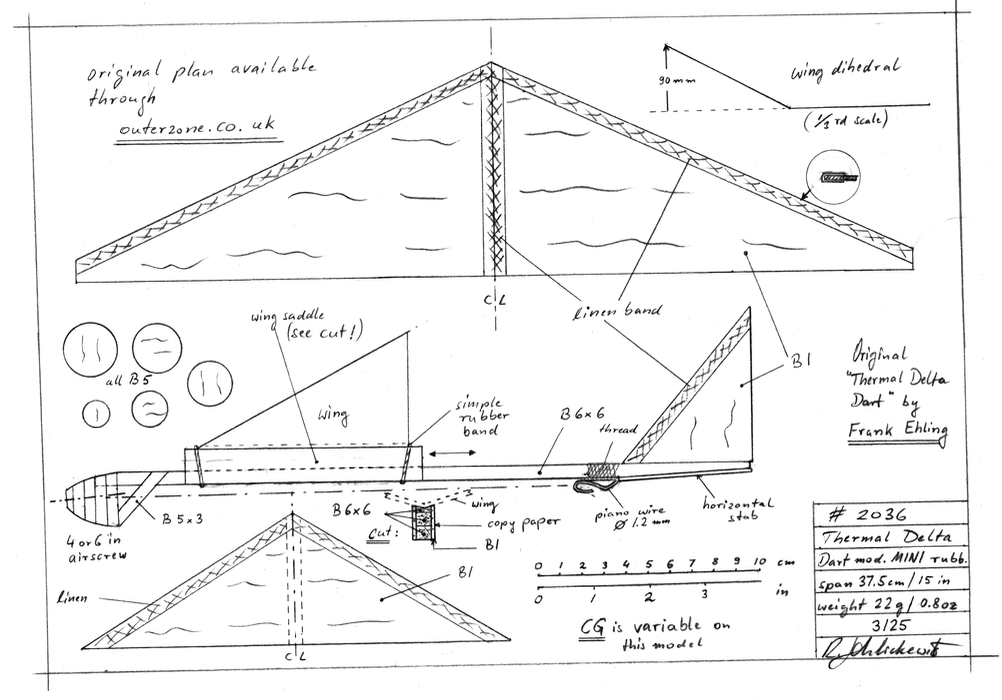
Span 37.5 cm / 14 ¾ in
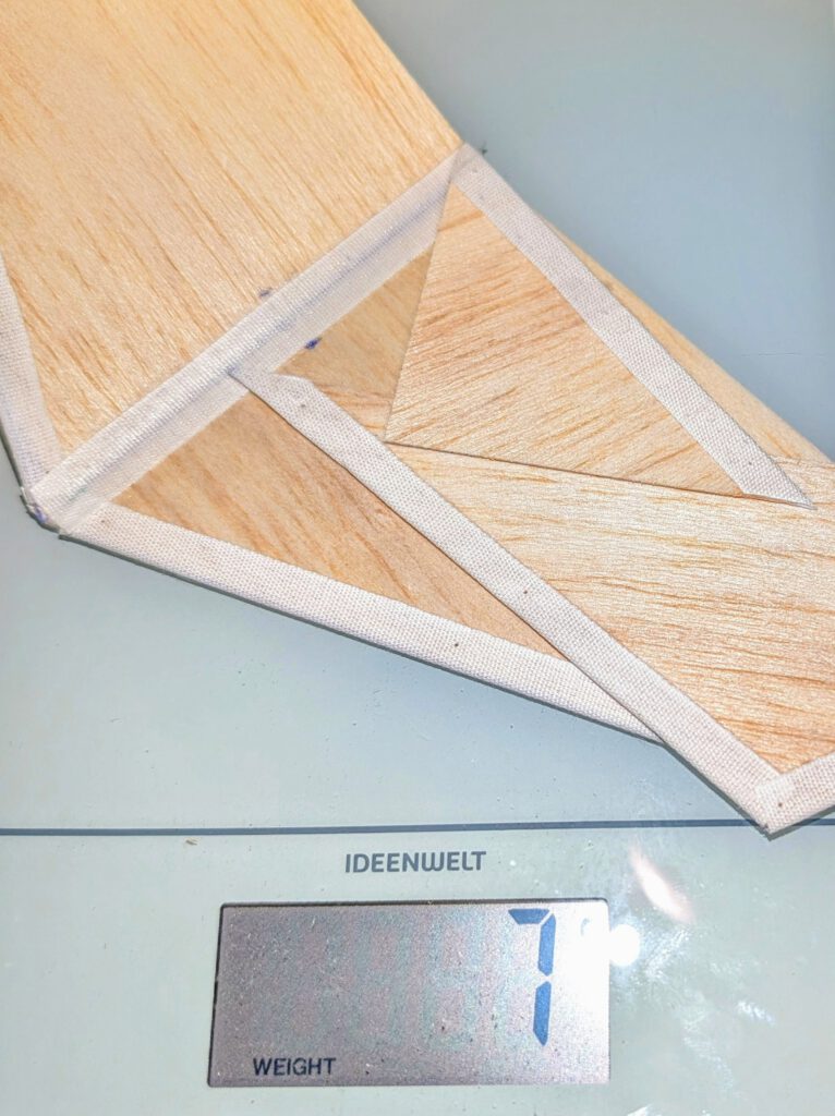
Weight 22 g / ¾ oz
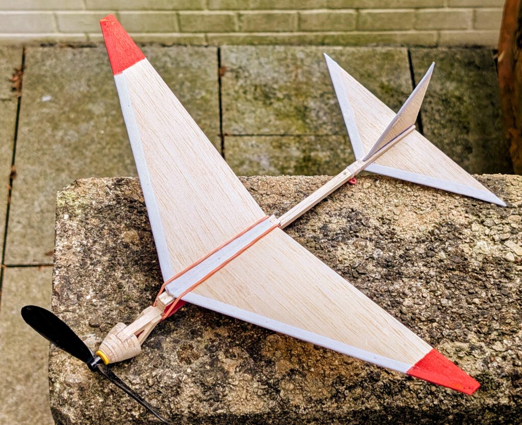
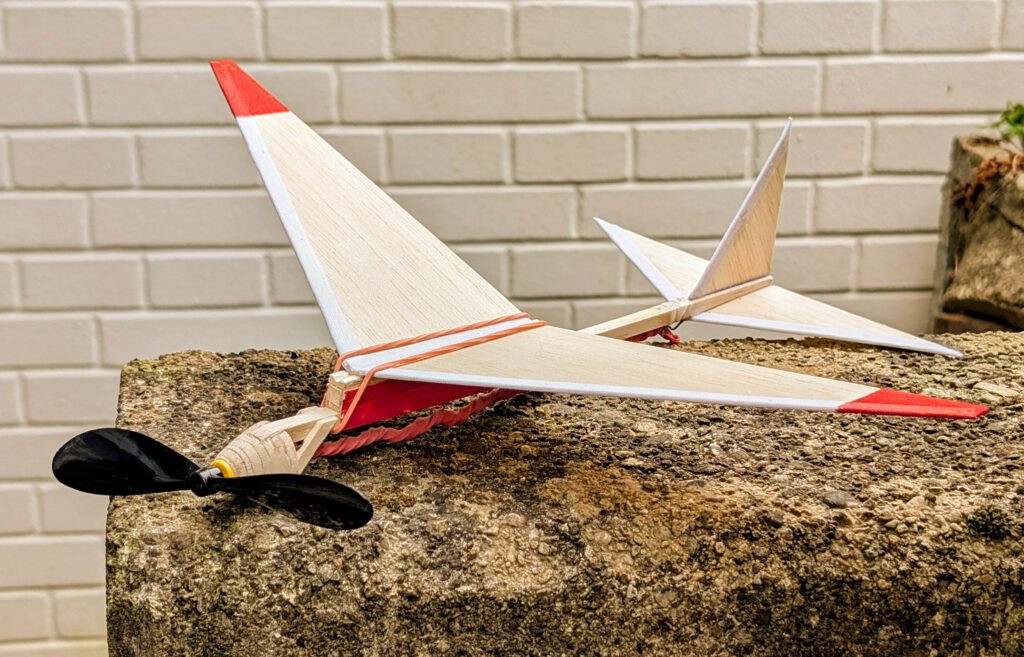
The model:
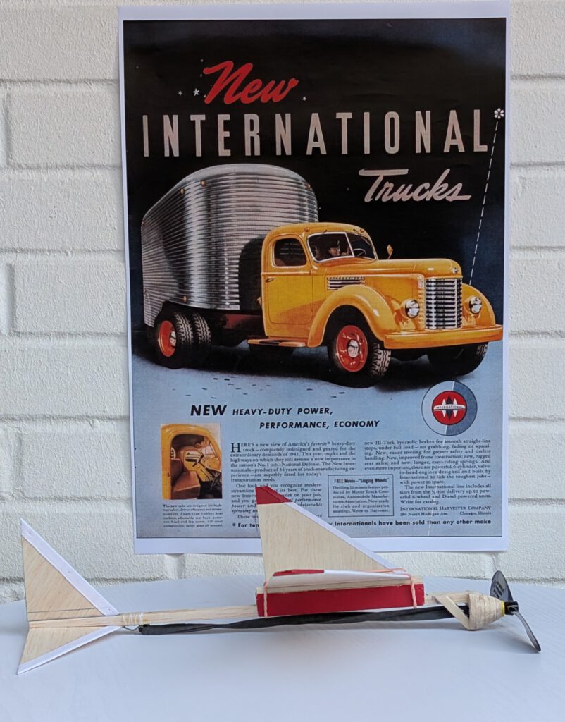
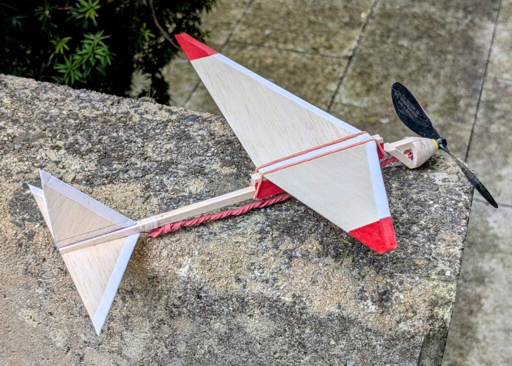
The original Thermal Delta Dart was a 24 in span rubber powered model by well known American model designer Frank Ehling from 1970. It was lightly built and could therefore reach heights where thermals could be encountered. Our model while retaining the outlines of the original was scaled back to a span of less than 15 in. It is light as well and capable of doing distances of up to 80 yards if built as shown and described here.
Building the rubber powered model Thermal Delta Dart mod.:
Materials:
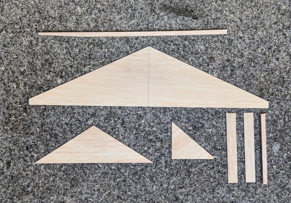
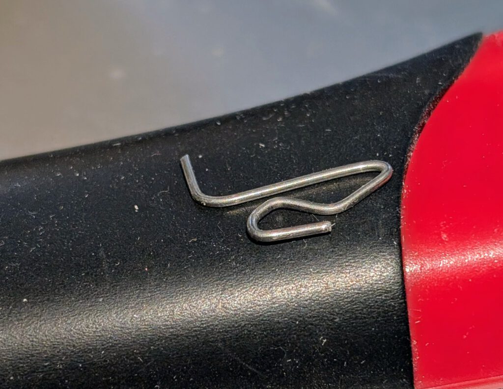
Fuselage: B stick 6 x 6; round nose parts: B 5; additional nose parts: B 5 x 3; rubber hook: piano wire 1 or 1.2 mm diameter; wing: B 1; wing saddle: B 6 x 6 and B 1; horizontal stabilizer: B 1; fin: B 1; linen band width 10-12 mm / ½ in; household rubber ring; solid tailor’s thread; ballast: small piece of scrap metal or lead; one commercial airscrew 4 in … 6 in diameter; black or red high quality rubber.
Assembly:
Cut out balsa parts in accordance to plan. Sand well. Apply colors at this stage if desired.
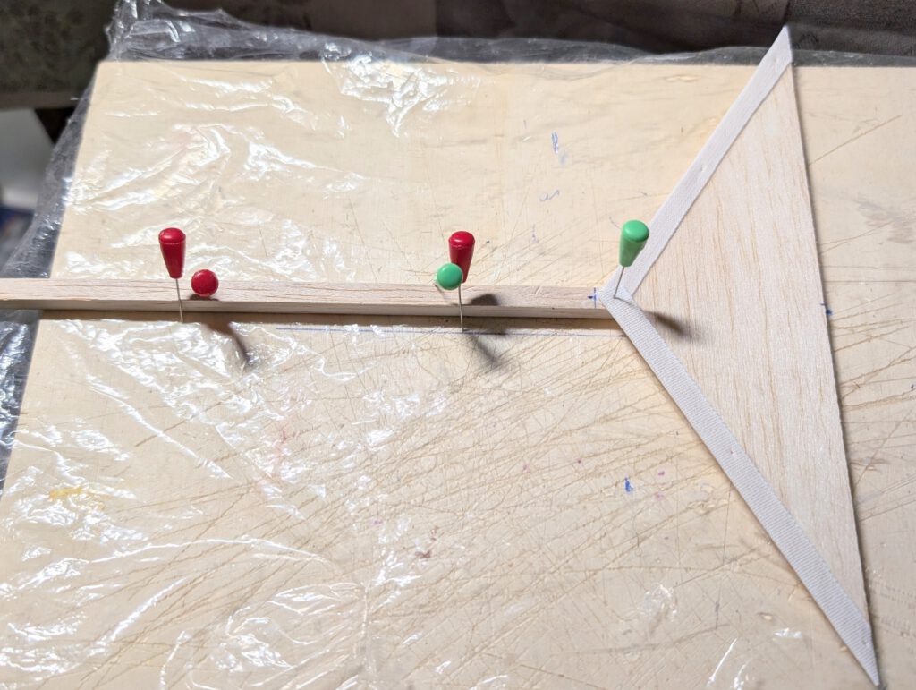
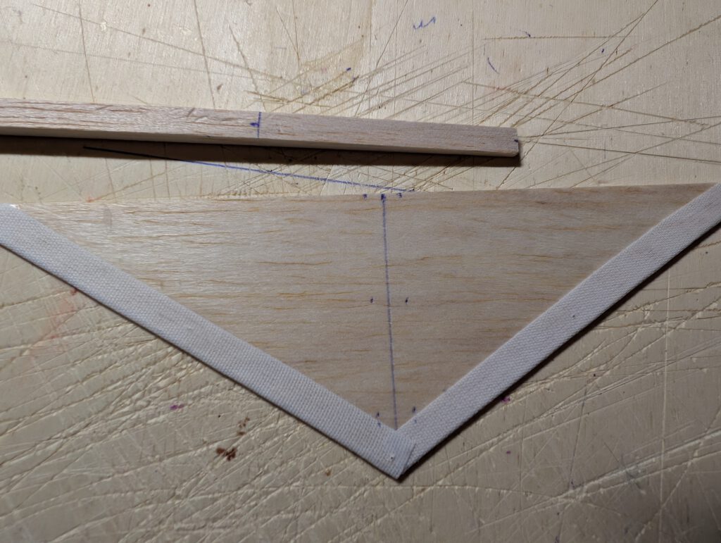
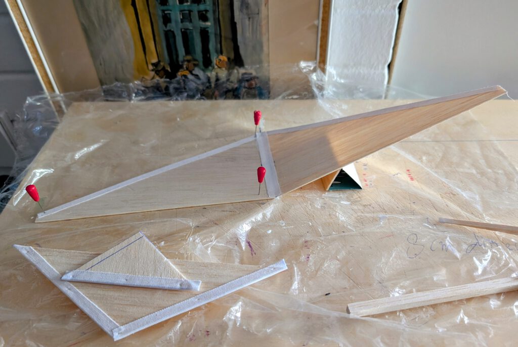
Wing:
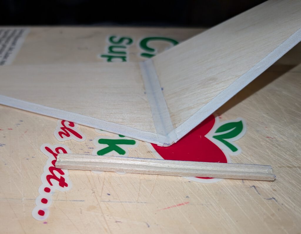
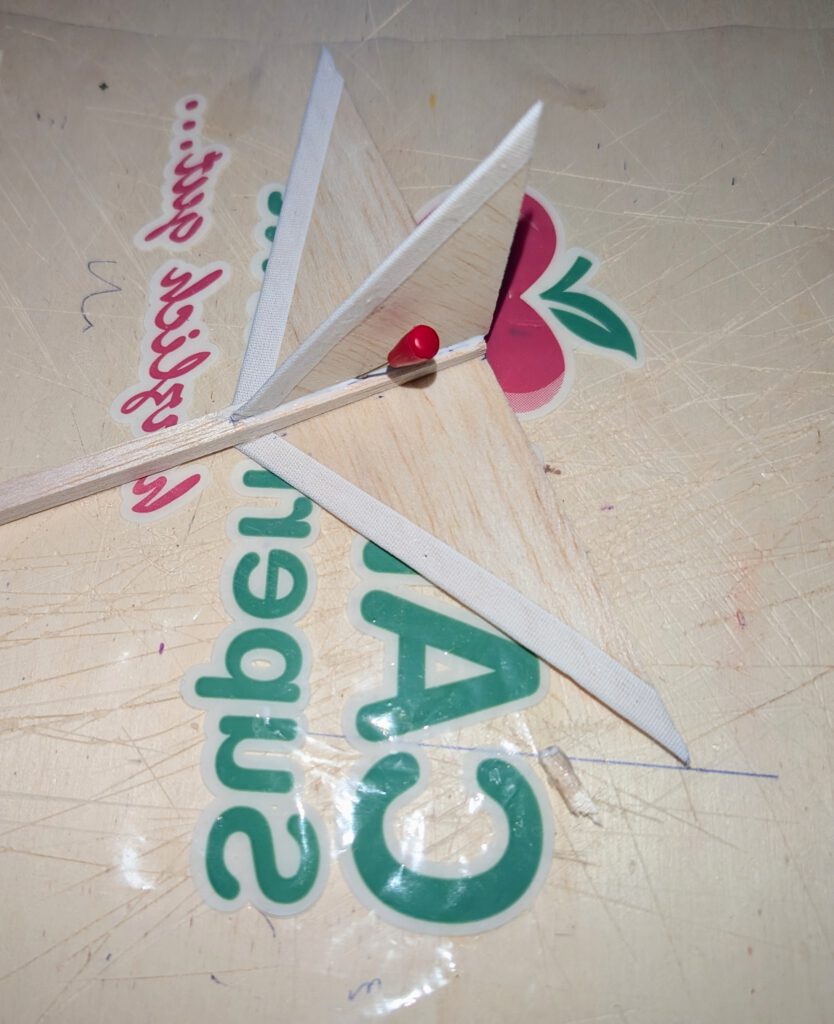
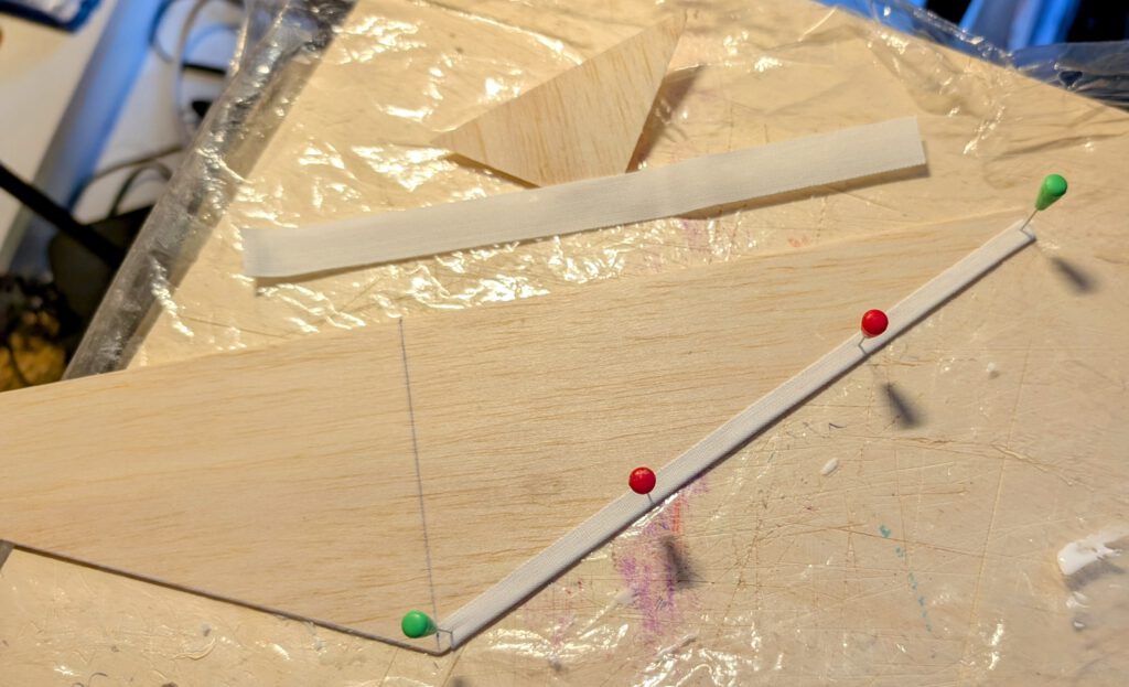
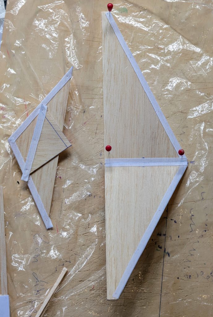
Wrap and cement linen band around leading edges of both wing halves as shown on plan. Wing consists of a right and a left wing-half. Fix right wing half on building board with pins. Underlay left wing half tip in accordance to required dihedral. Join both halves and cover wing center area with linen band. Let dry. If wing has the tendency to rest only on one side then it is too heavy on this side. To compensate the imbalance disperse a small amount of white wood glue on the opposite wing half’s underside tip area and let dry. Do it if necessary twice until balance is obtained.
Fuselage:
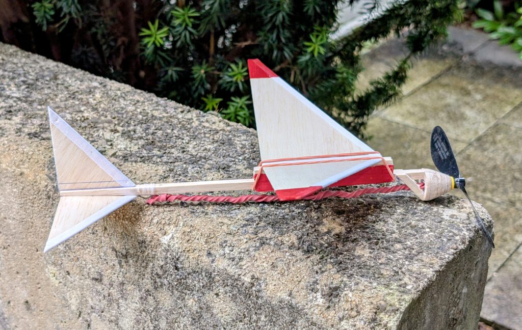
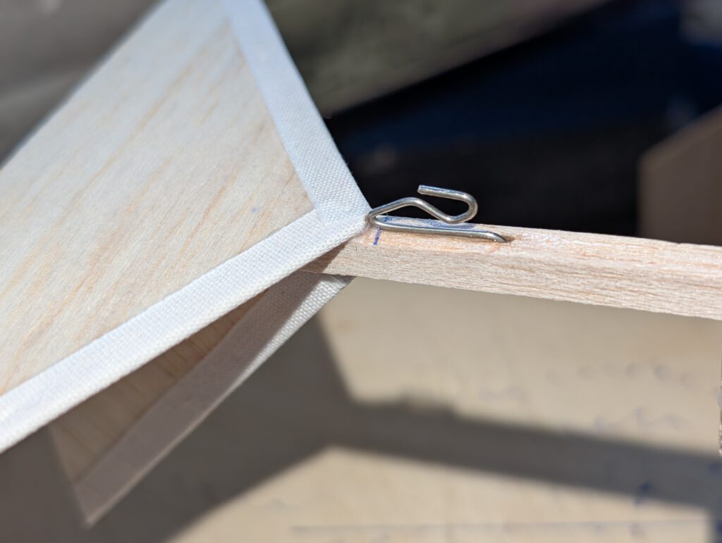
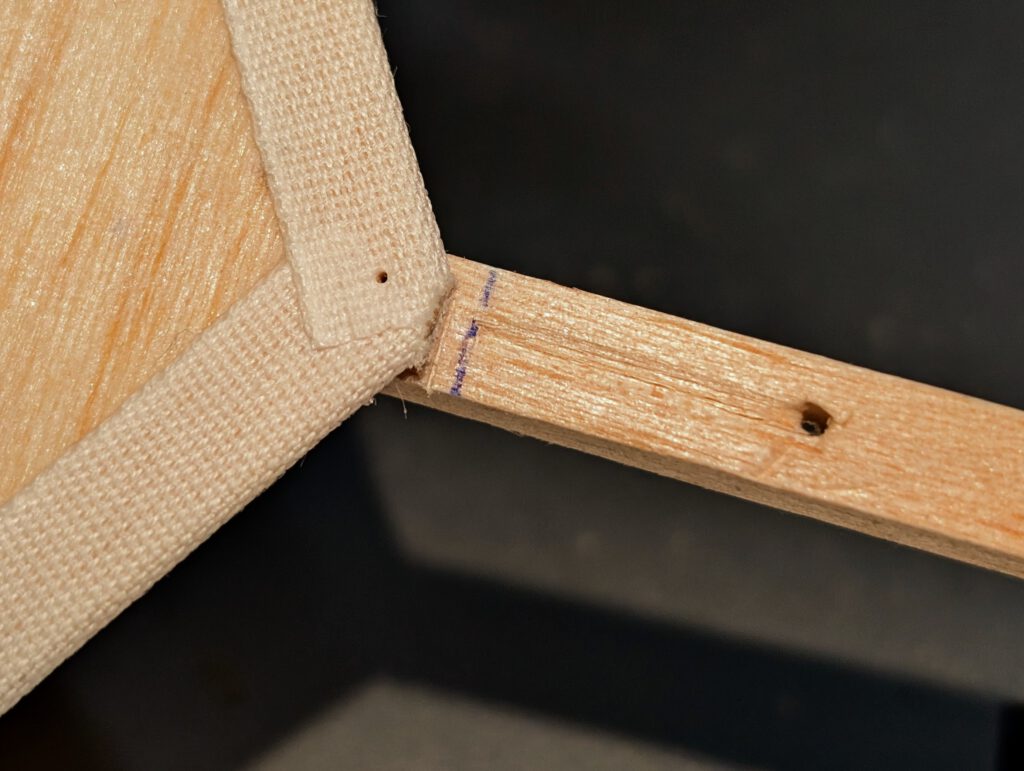
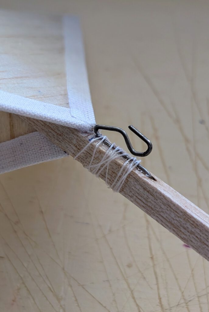
Bend as shown on plan piano wire into given hook shape. Wrap thread around fuselage stick and wire hook as shown on plan. Add cement and let dry.
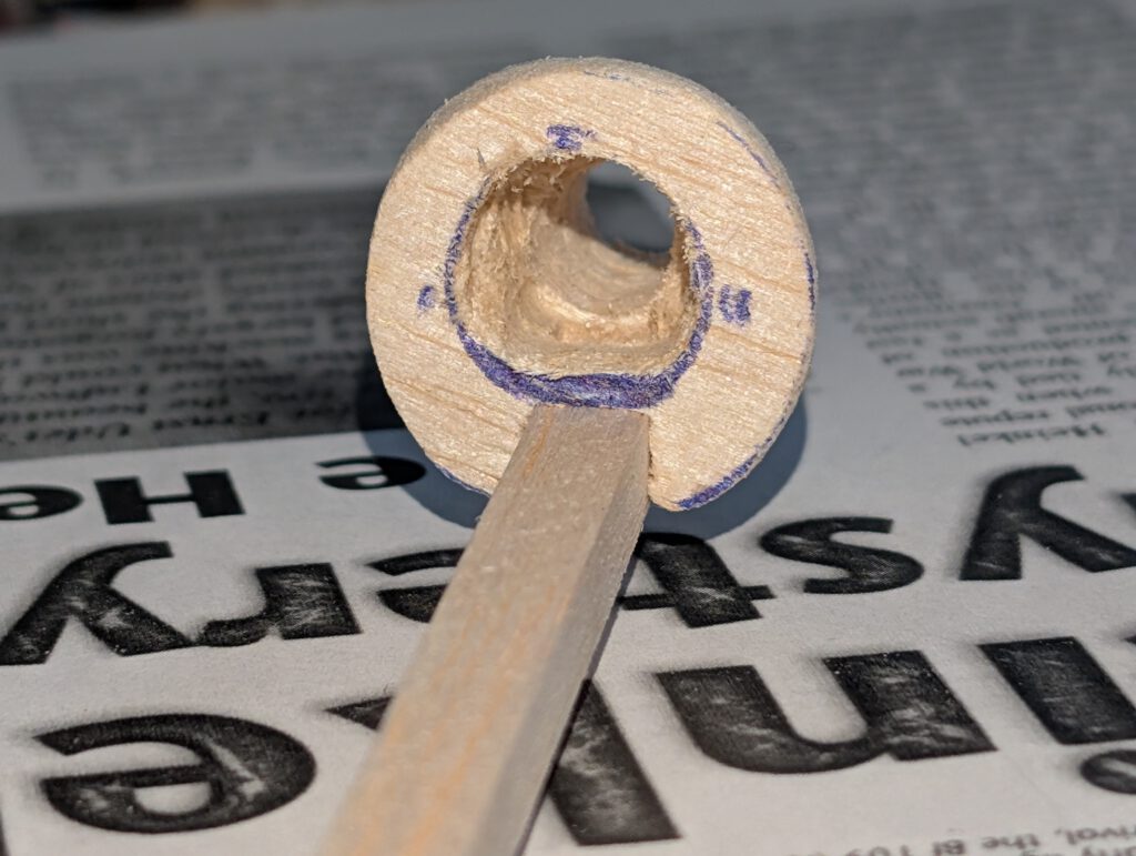
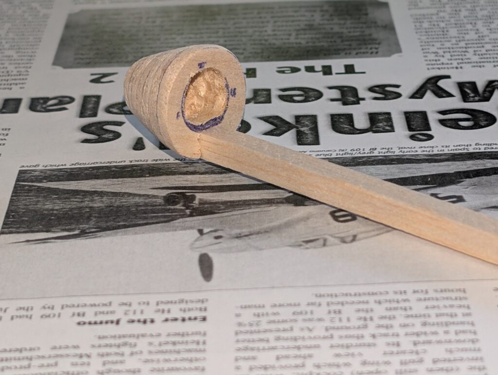
Cement round nose parts one on the other as shown on plan and let dry. Sand well than treat this part with balsa putty. When dry sand again. May be this procedure has to be repeated. When the nose part is smooth you can start to carve out opening which will hold prop-bearing. Start from behind and do it not in a hurry. A little electric drill machine can be useful.
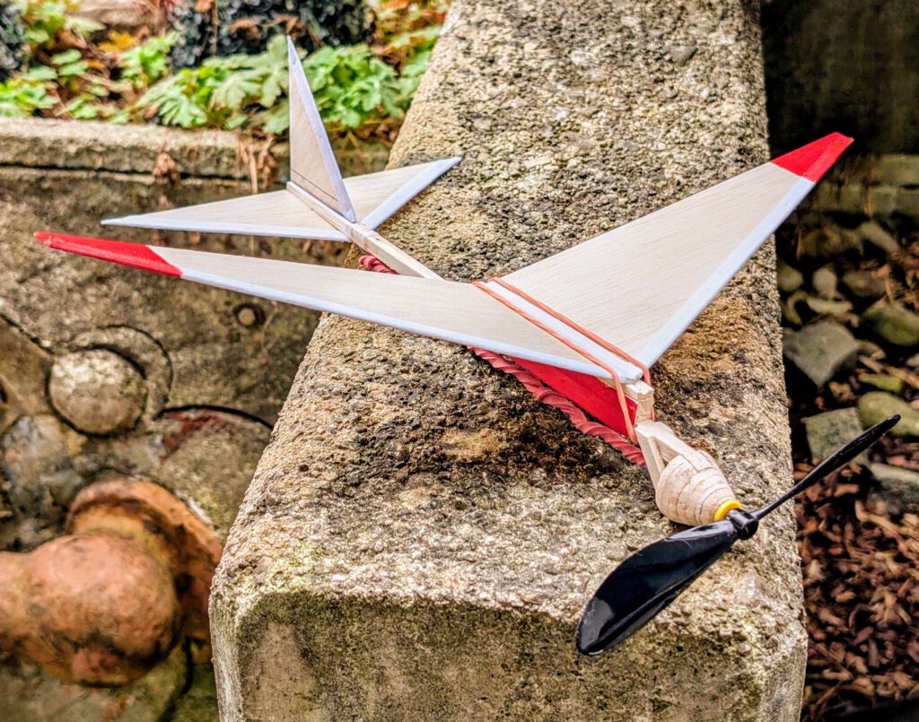
Cement nose on fuselage according to photos. Add B 5 x 3 part as on plan and let dry.
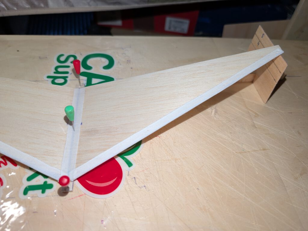
Empennage:
Wrap and cement linen band around leading edges of both fin and horizontal stab as shown on plan. Let dry.
Cement fin on fuselage using pins to hold in place. Always visual check twice that symmetry is obtained.
Cement horizontal stabilizer onto place shown on plan using pins to hold in place. Visual check symmetry from all sides. Let dry.
Final Assembly:
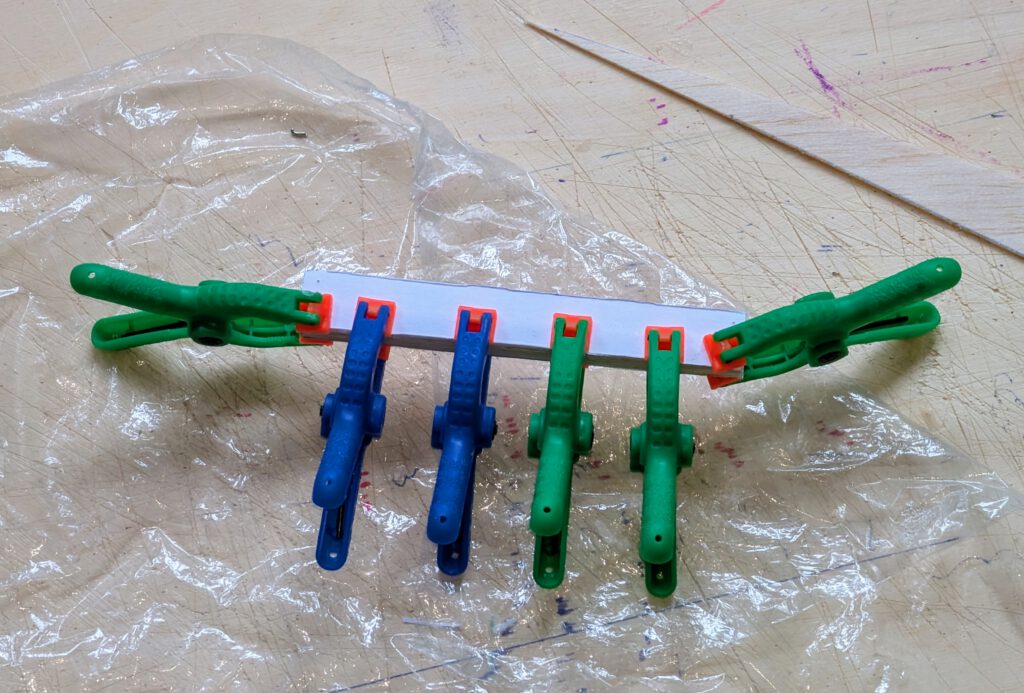
Build wing saddle from B 6 x 6 and B 1 material as shown on plan and let dry. A small piece of copy paper cemented on B 1 parts prevents saddle side walls from breaking — so add it. Cement wing on saddle using if necessary pins to hold in place. Doublecheck visually symmetry. Let dry.
Attach wing with saddle on fuselage using rubber ring to hold tight. Find out CG by pushing wing assembly back or forth. Add if necessary a small piece of lead or scrap metal.
Remember correct center of gravity (CG) is essential for successful flights.
¡Muchos vuelos exitosos! (Ϻного успешни полети!)
Leave a Reply