
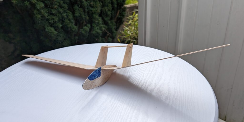
Span 59 cm / 23 in
Weight 13 g / 0.46 oz
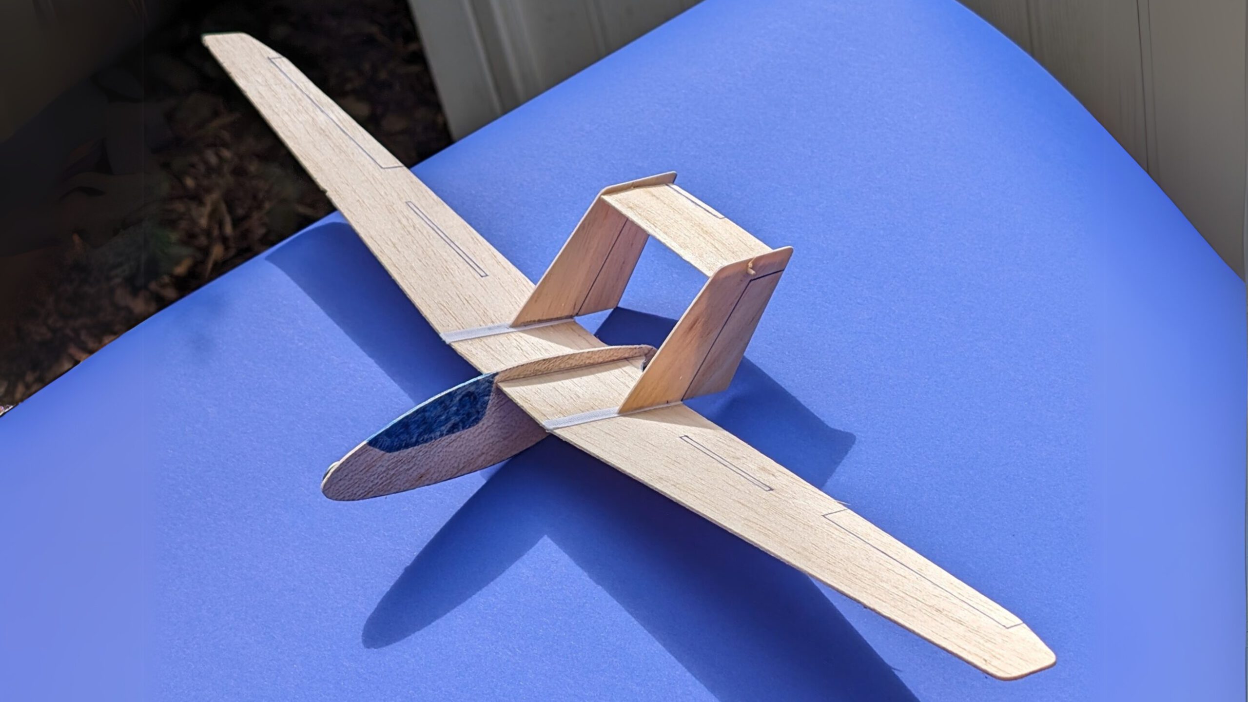
The original Fs-26 is a German single seat motor glider which first flew in 1970. Only one was built mainly for testing purpose. The plane although ressembling a flying wing is indeed a cantilever high-wing monoplane with monocoque nacelle fuselage, twin fins and an all-moving tailplane. Powered is the Fs-26 by a small 26 hp Solo-Hirth piston engine in the rear end. Wingspan measures 12.60 m / 41 ft 4 in and length 3.94 m / 12 ft 12 in; gross weight is 360 kg / 793 lb and maximum glide ratio: 24.
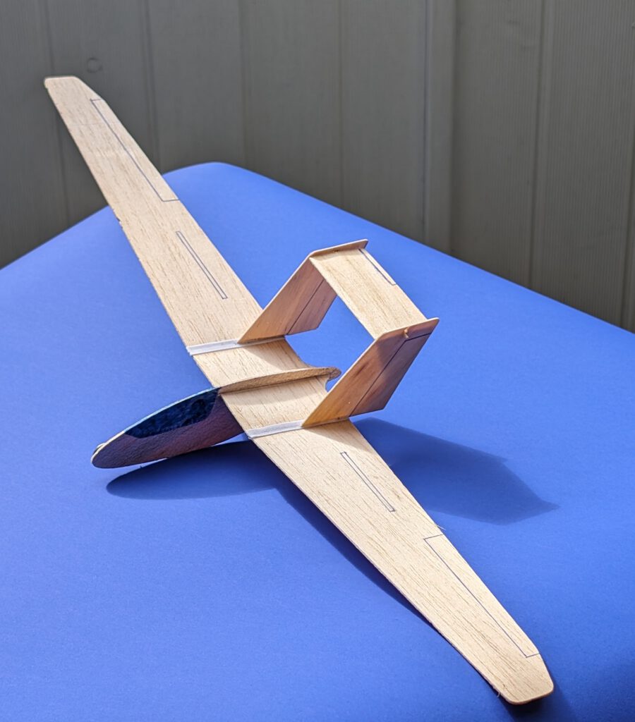
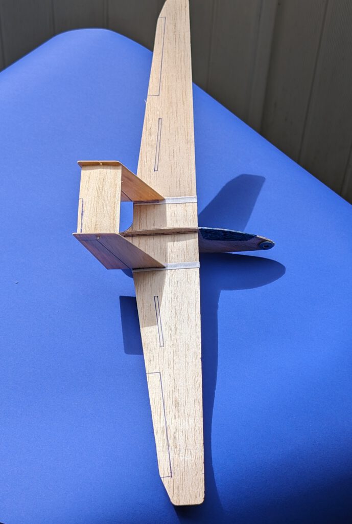
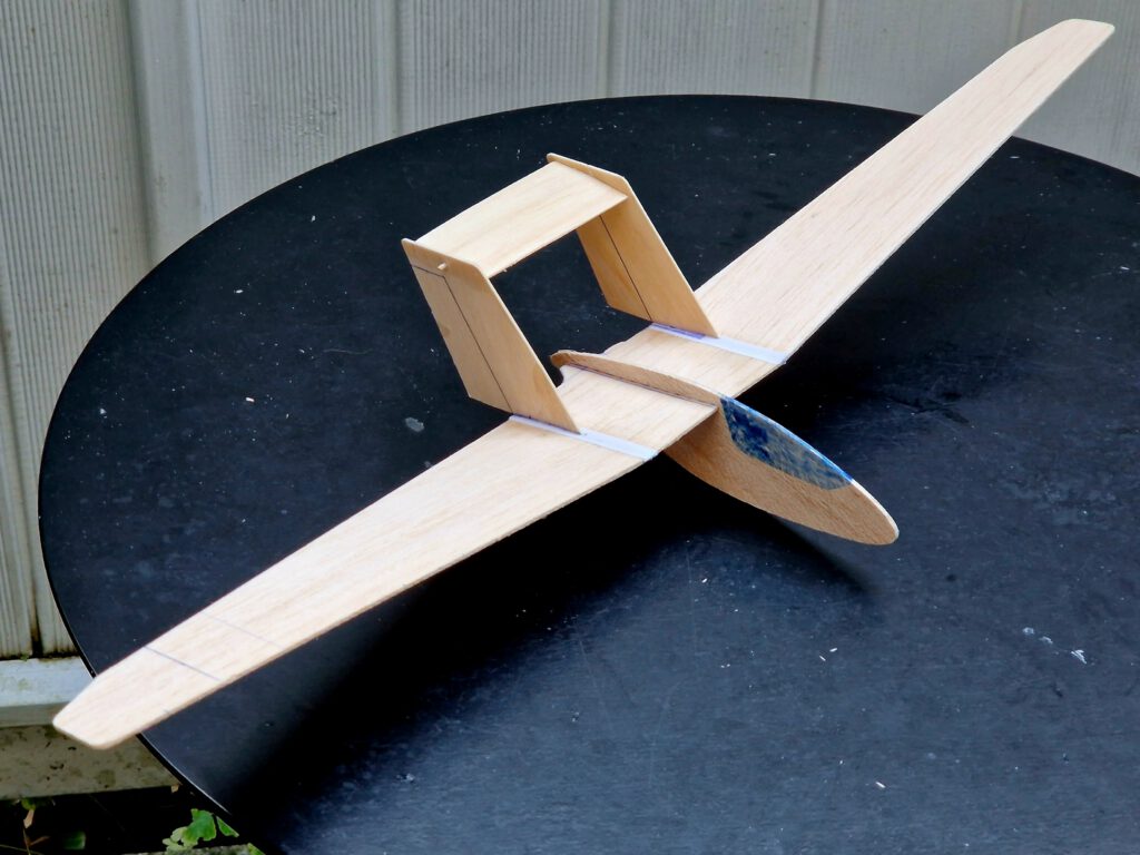
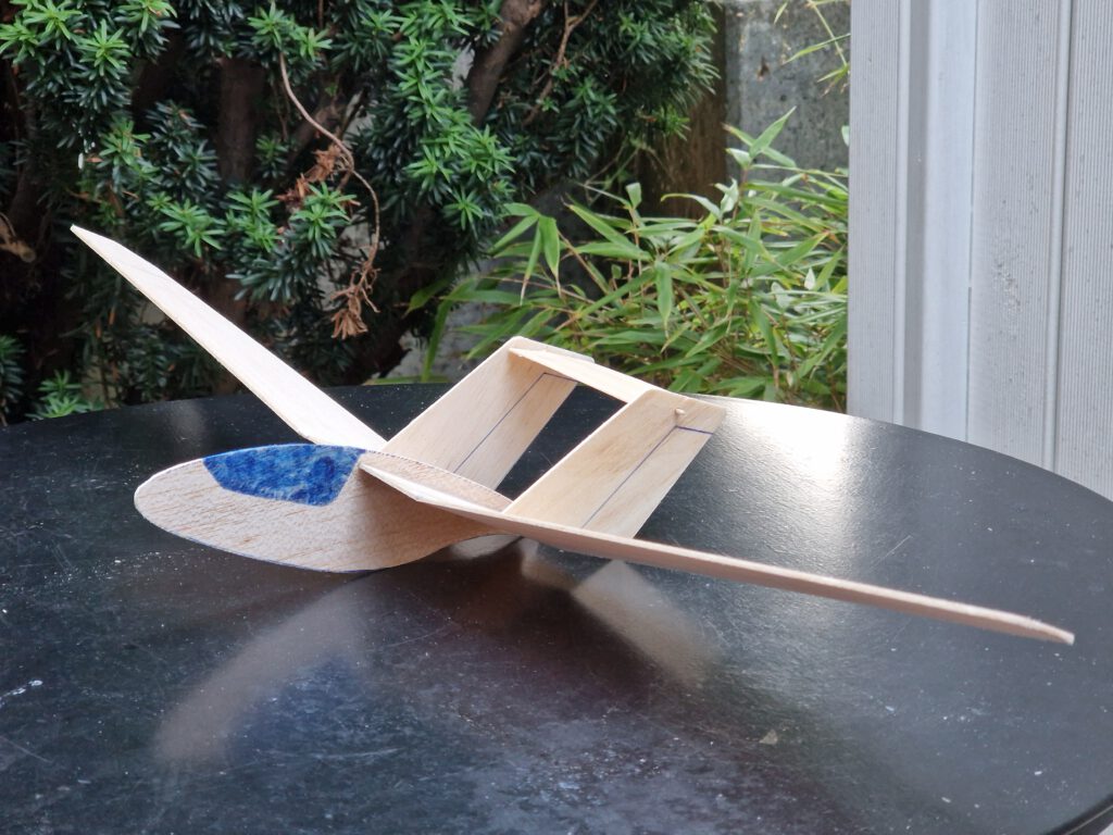
Building the balsa sheet chuck glider Akaflieg Stuttgart Fs-26.
Materials:
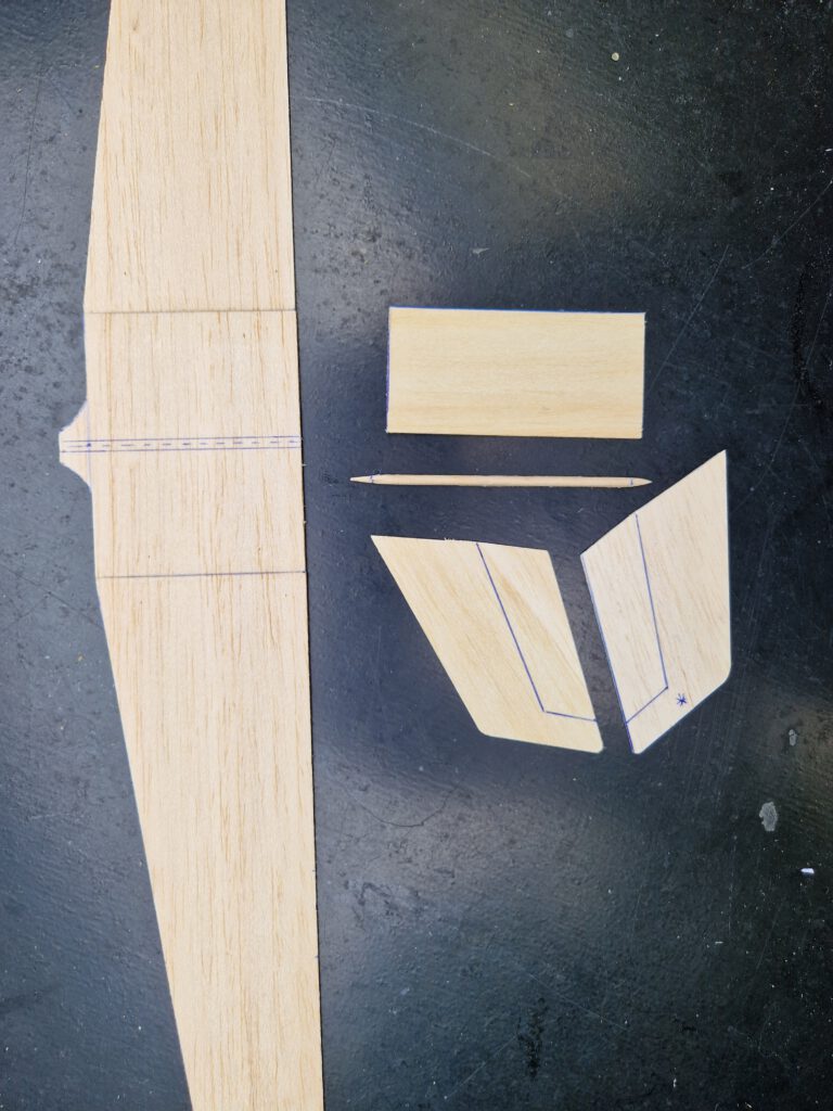
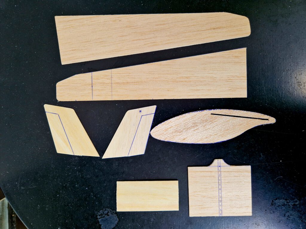
Fuselage: B 1.5 or B 2; wing: light B 1.5 or hard B 1; Fins: B 1; horizontal stabilizer: B 0.8 or 1 plus a commercial toothpick; linen/cotton band width 6 mm / ¼ in; Ballast: small piece of lead or scrap metal.
Assembly:
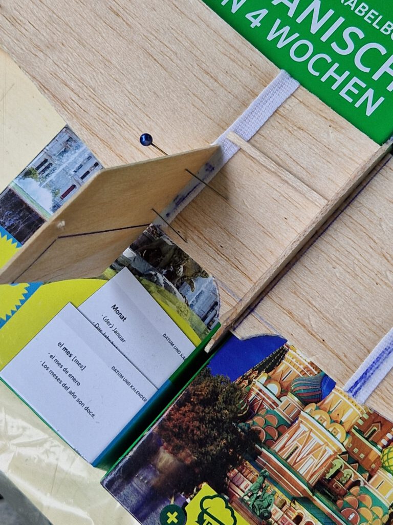
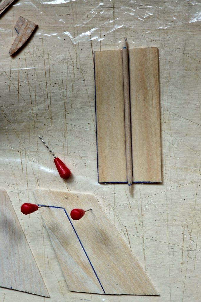
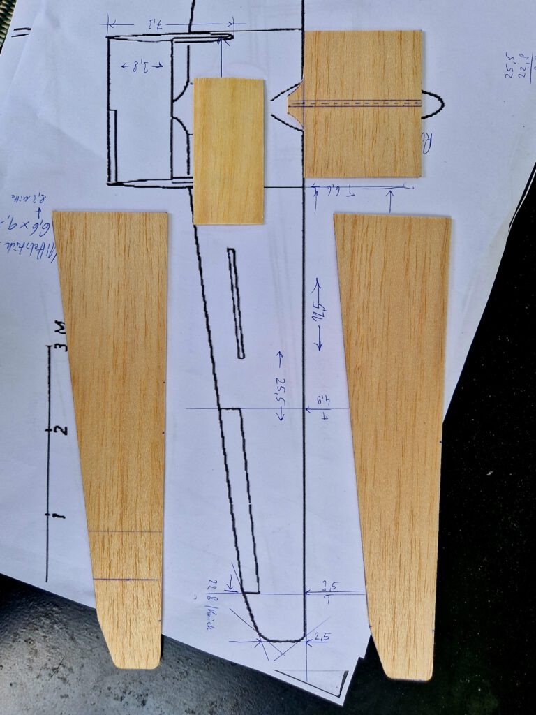
Cut out all balsa parts. Make slot for wing. Drill holes in fins. Sand well. Transfer outlines of canopy, rudders, elevators, flaps ec from paper to wood with pen (photo).
Wings:
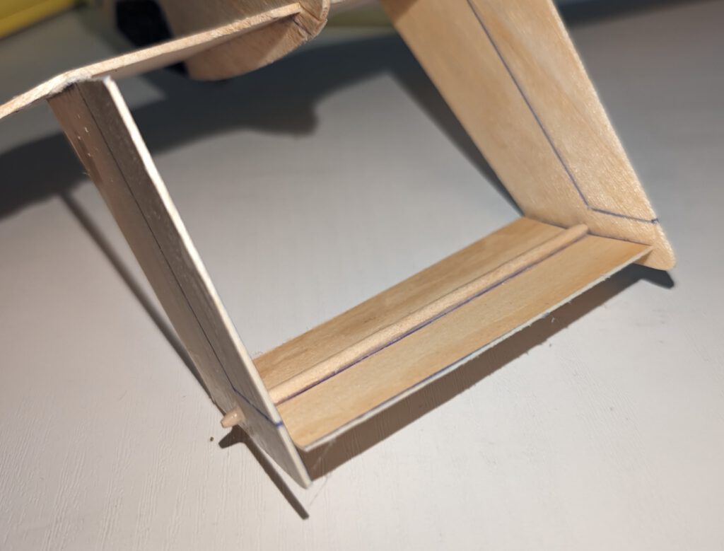
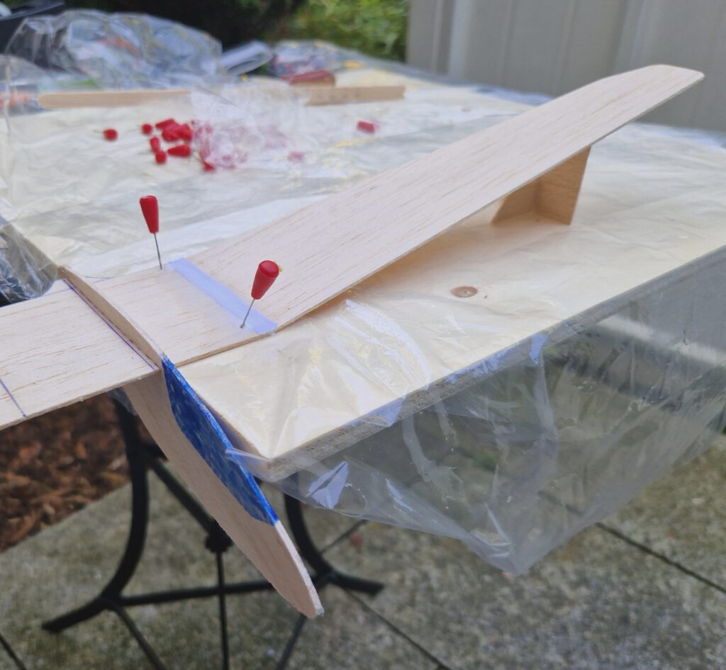
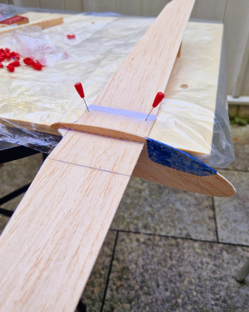
Fix wing center section on building board with needles. Underlay left outer wing according to given dihedral and cement (photo). Linen tape should be used to strengthen joining area. Reinforced balsa sheet joints are less prone to deforming. Let dry. Repeat procedure with right wing half.
Empennage:
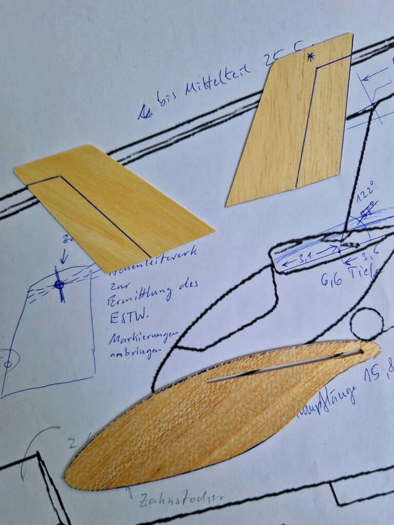
Cement toothpick to horizontal stabilizer underside in position given on plan (photo).
Final Assembly:
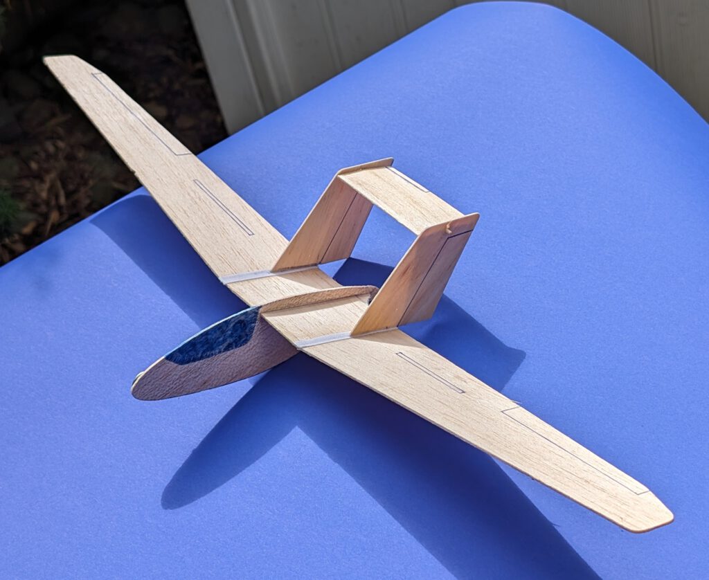
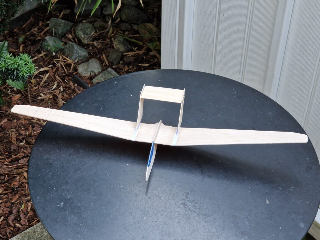
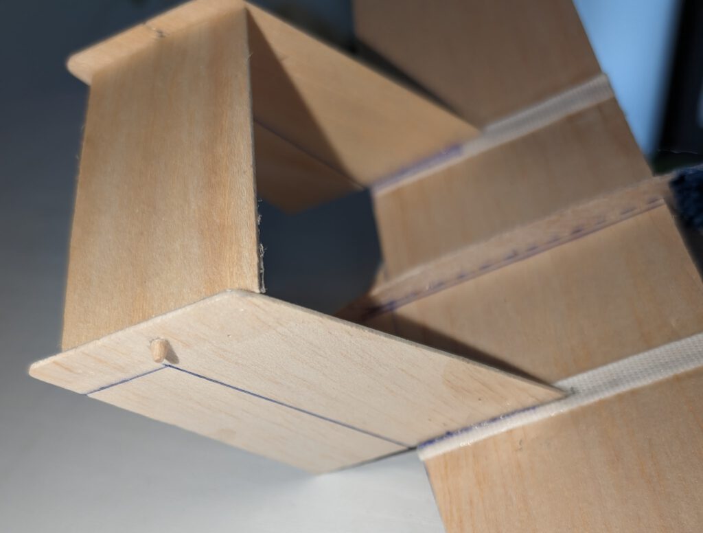
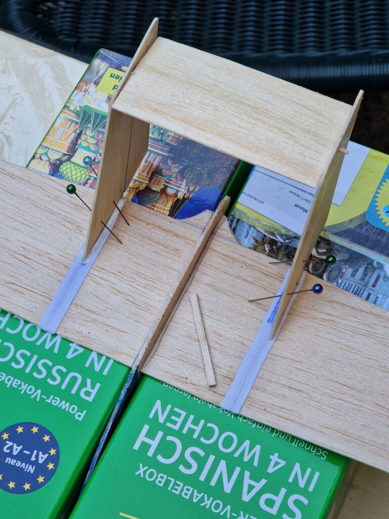
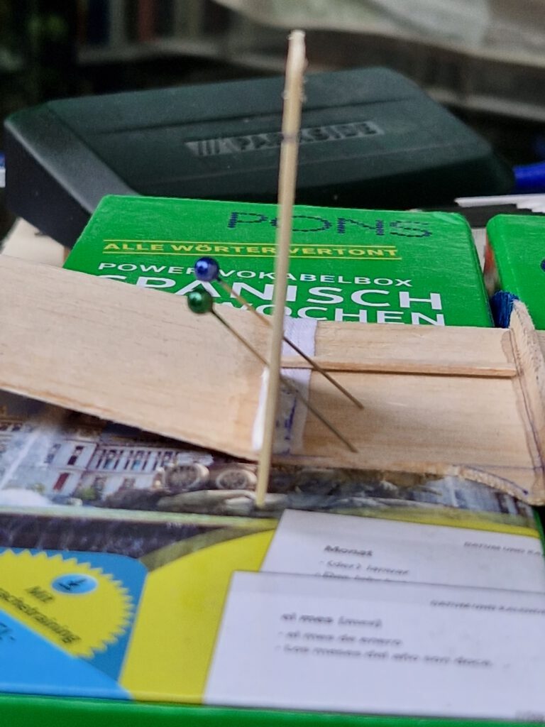
Use for this step two equal sized old books or two strong cardboard boxes (photo). Position fuselage between the books/boxes and slide wing into fuselage slot using needles to hold in place. Visual check from all sides to obtain best possible symmetry. Now cement wing to fuselage and let dry.
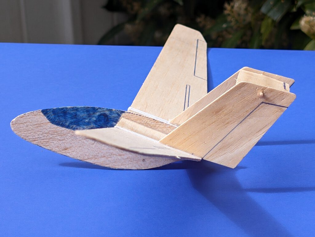
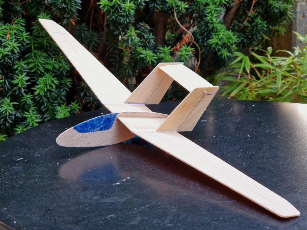
Wing center section still rests on both books or cardboard boxes and fuselage hangs between the books. Now set left fin on its place on wing and cement it. Must be vertical towards wing center section (photos). Let dry. Repeat procedure with right fin. Let dry.
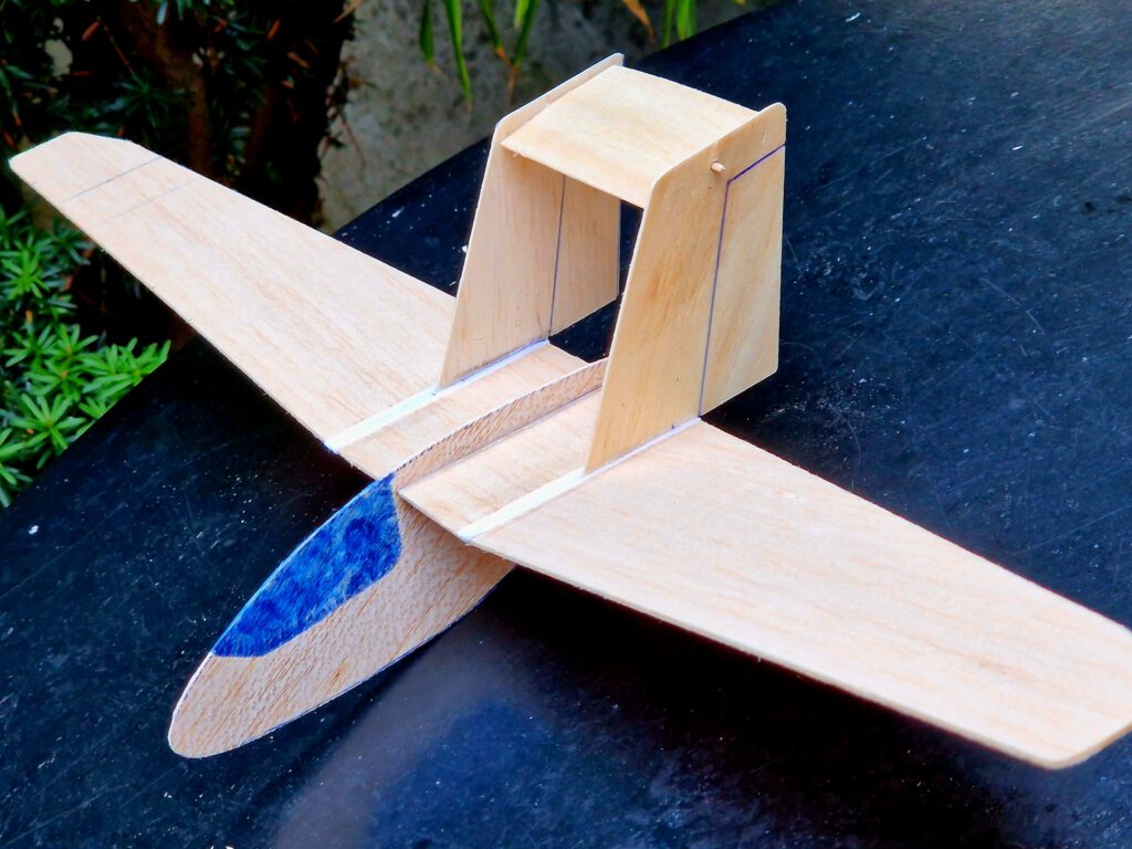
Bend upsides of the fins slightly outwards and position toothpick tips of horizontal-stab-assembly into the holes of the fins (photo). Don’t cement yet.
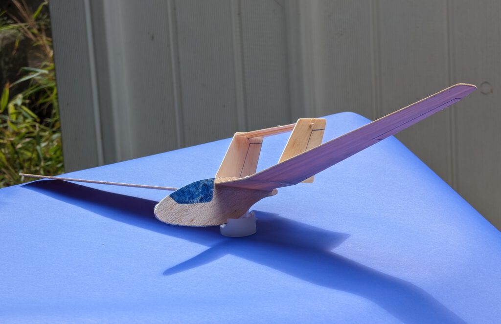
Balance model in accordance to given CG on plan.
Now start test flying. Find out what angle of incidence horizontal stab must have to result in best flight characteristics – only then finally cement.
Buon volo! (гарного польоту!)
Leave a Reply