
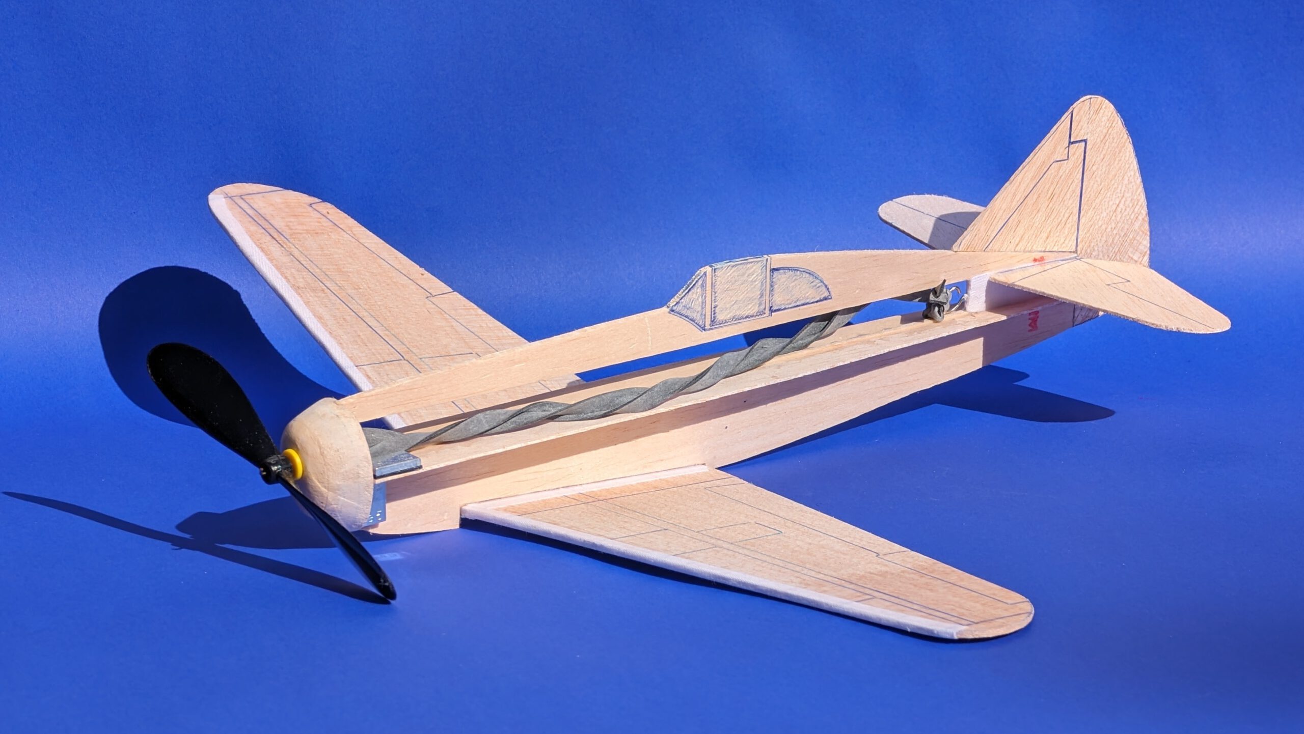
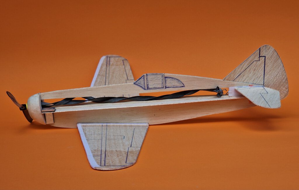
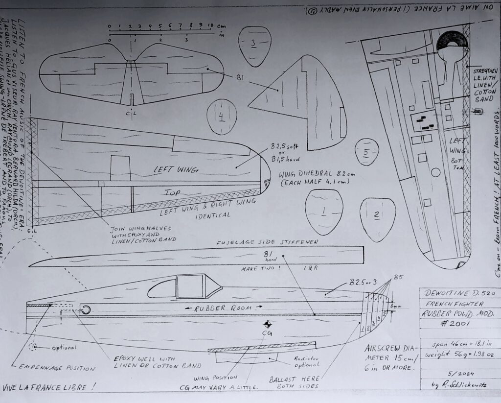
Span 46 cm / 18 in
Weight 56 g / 2 oz
The Dewoitine D.520 was a French fighter aircraft of the Second World War. First flight took place in October 1938 and only in 1953 retirement of the plane occured. Operators of the Dewoitine were not only France but Bulgaria, Italy and Nazigermany. The D.520 had a wingspan of 10.2 m / 33 ft 6 in and a length of 8.6 m / 28 ft 3 in. Gross weight was 2,677 kg / 5,902 lb and powerplant a Hispano Suiza 12 Y-49 piston engine of 950 hp. The D.520’s manoeuvrability was considered to be superior compared to that of the nazi Mess. Bf-109 E by being a bit slower. All together around 900 Dewoitine D.520s were built.
Note: My plan of the D.520 was published in 2024 by OUTERZONE VINTAGE & OLD-TIMER PLANS. See https://outerzone.co.uk/plan_details.asp?ID=15325
Further note: I offer two plans of this model, one with built-in rubber motor (here) the other for my rubber power unit (RPU) 3001.
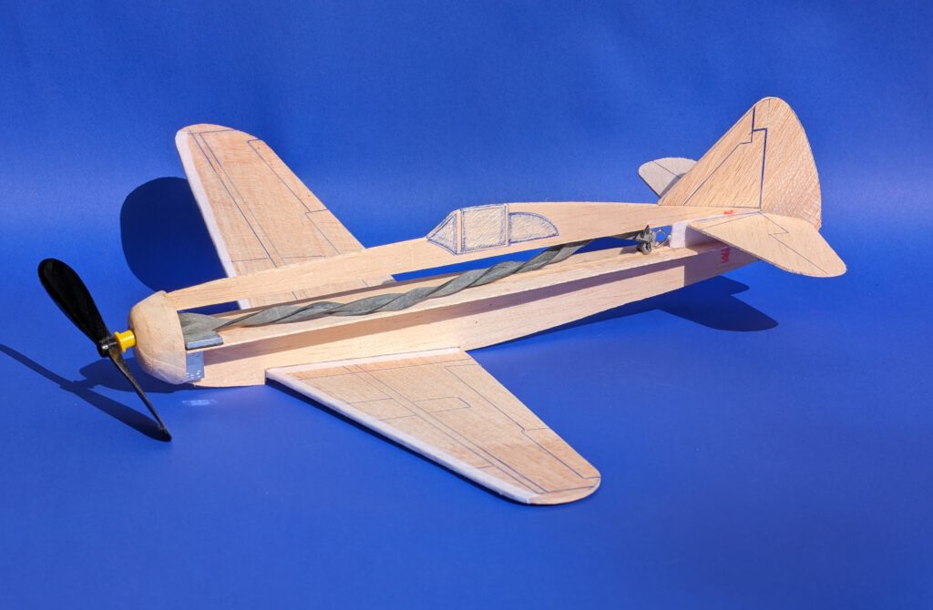

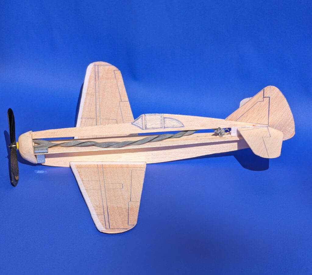
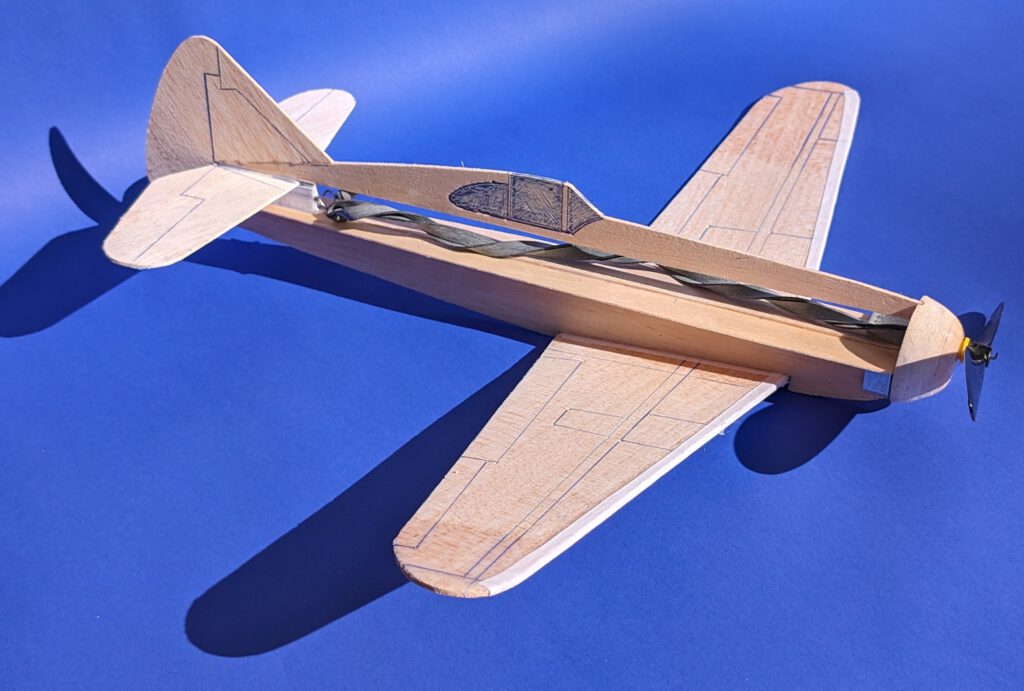
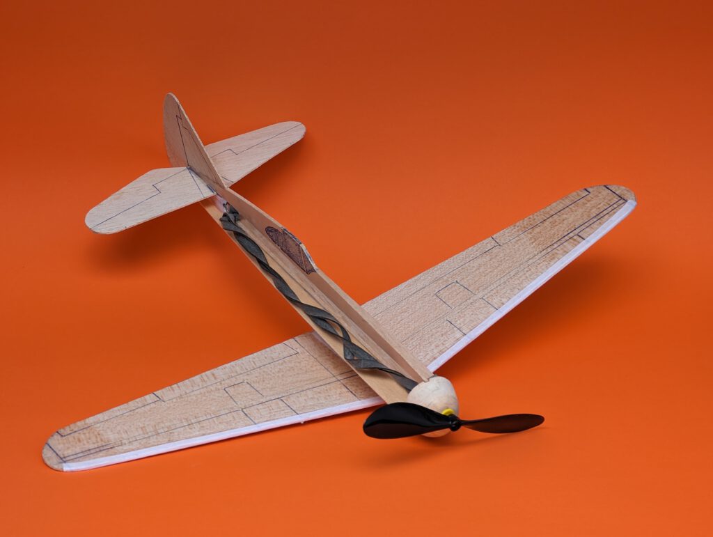
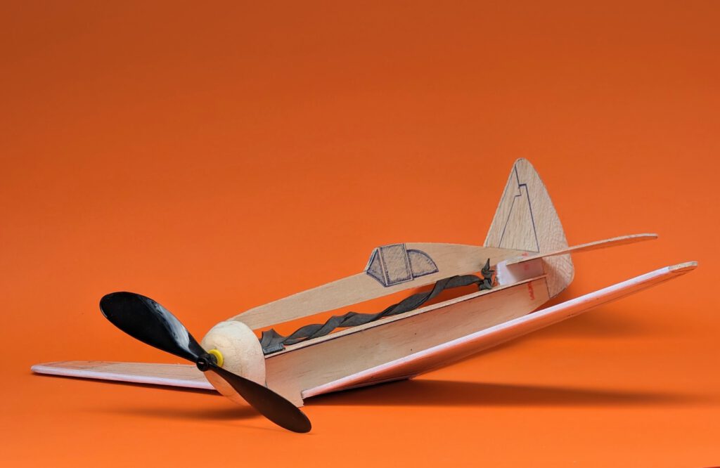
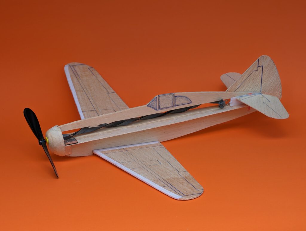
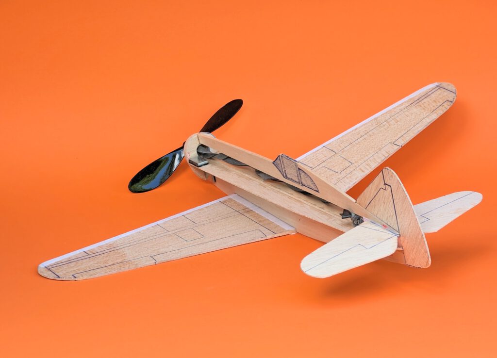
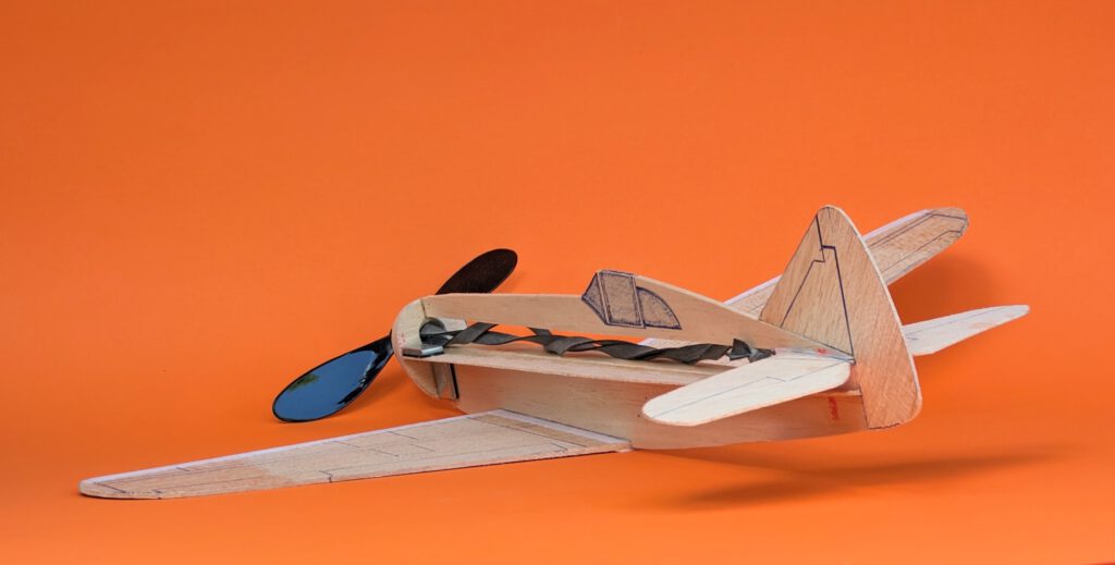
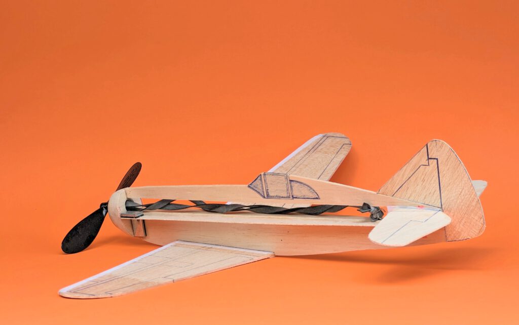
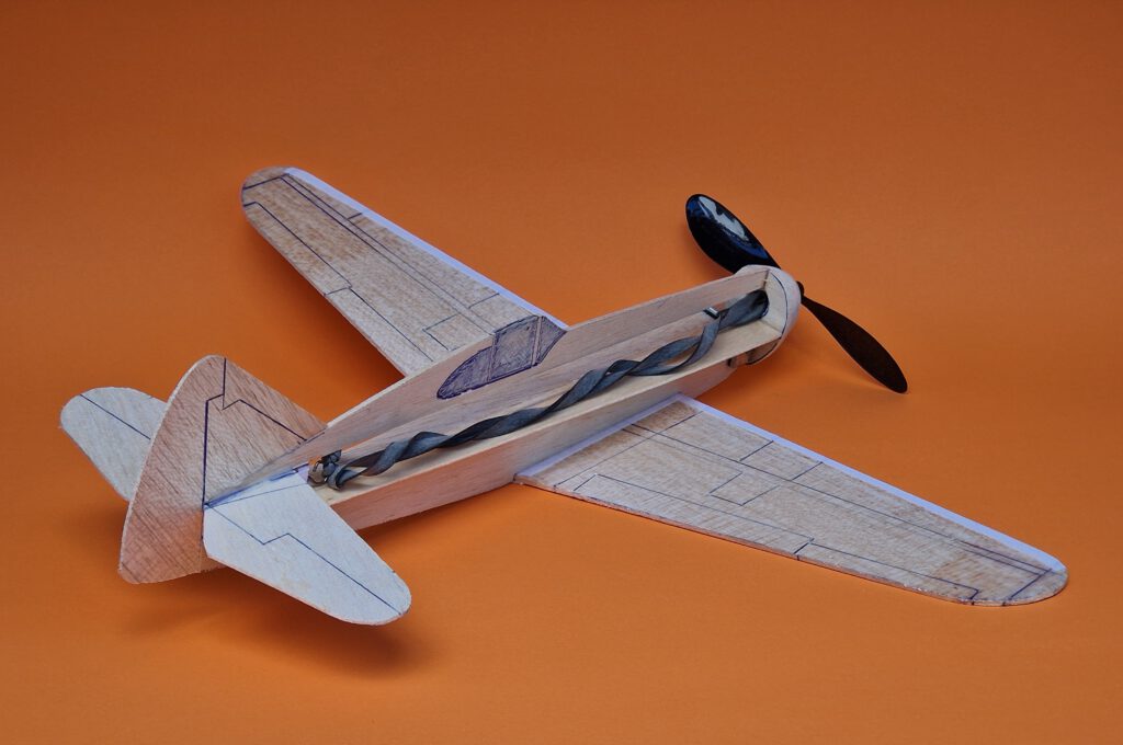
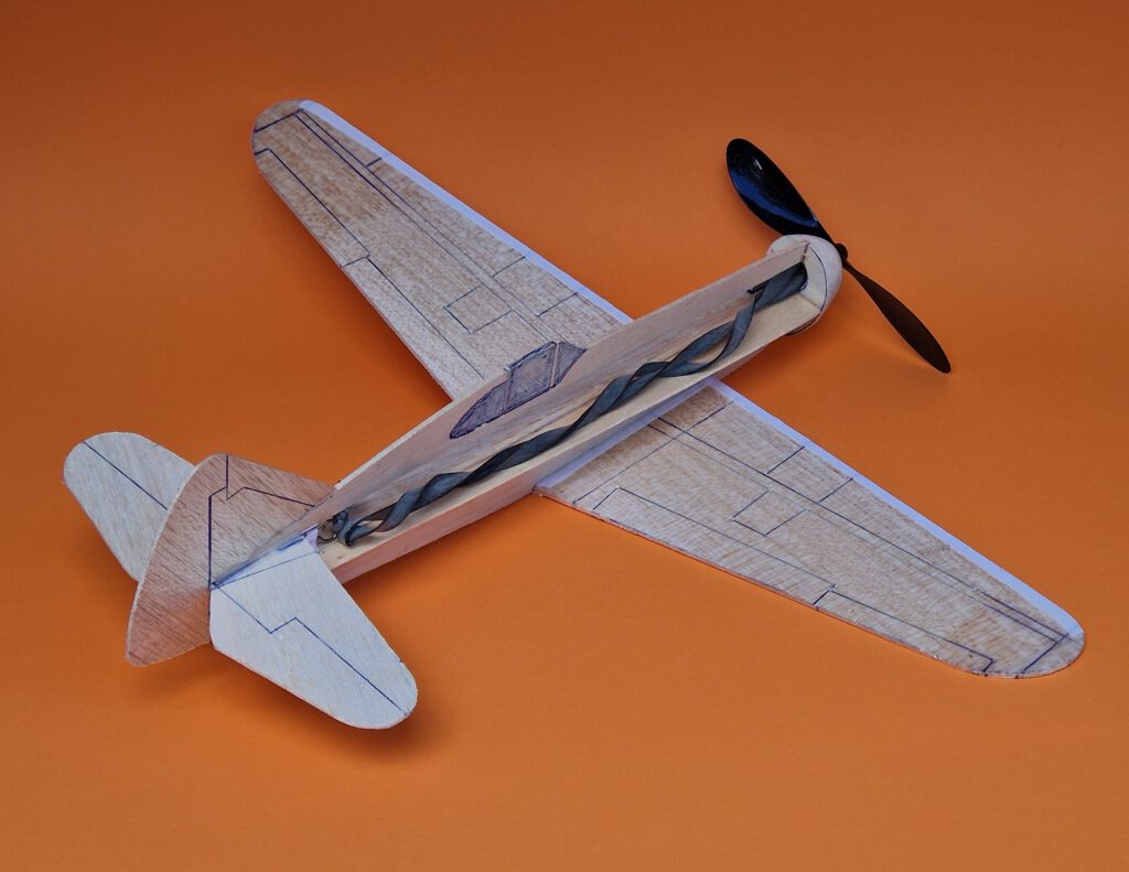
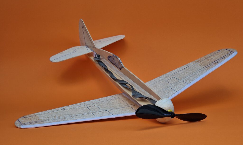

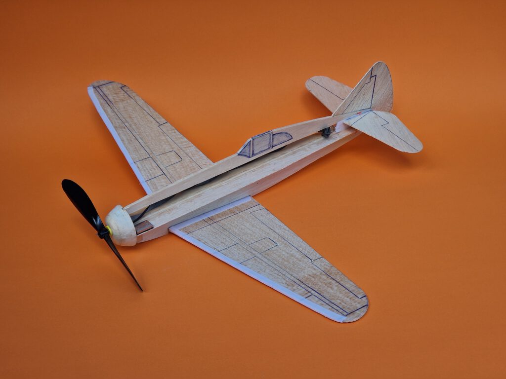
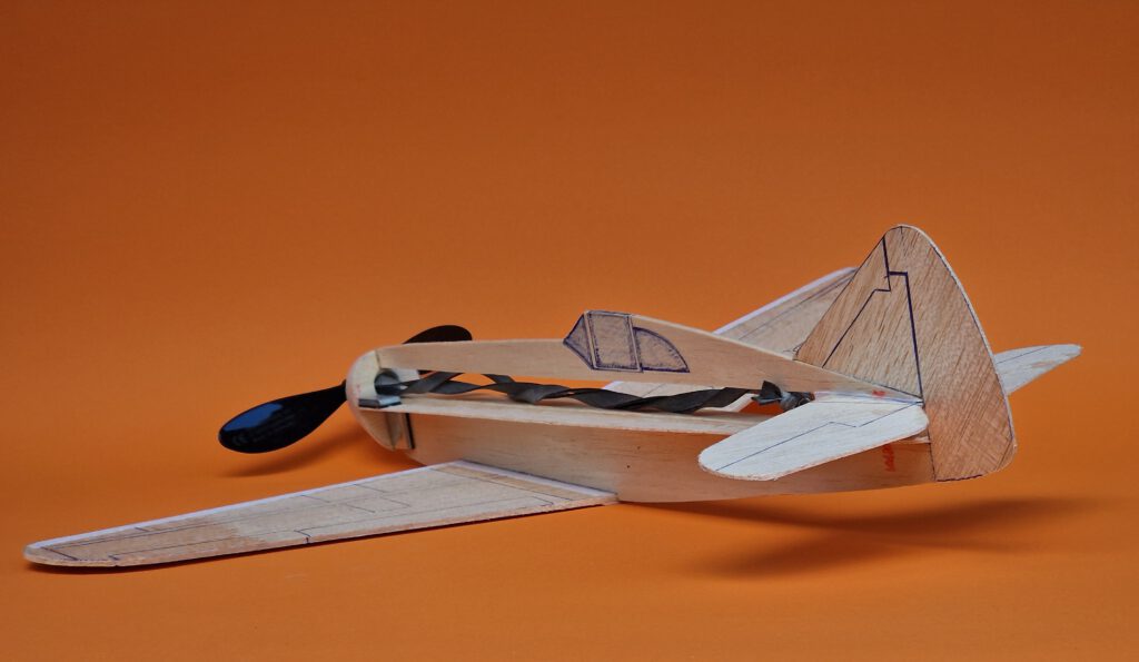
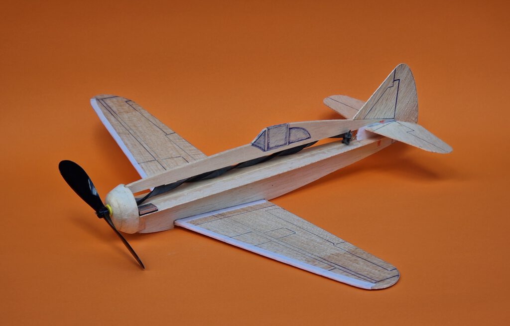
Building the rubber powered balsa profile-fuselage model Dewoitine D.520.
Materials:
Fuselage: hard B 2.5 or 3; fuselage side stiffener: B 1; fuselage nose parts: B 5; rubber hook: piano wire 1.2 or 1.5 mm diameter; wings: B 2; horizontal stabilizer: B 1 or B 1.5; fin: B 1 or B 1.5; linen band width 10 or 12 mm / ½ in; ballast: 15 g / ½ oz steel or lead; one commercial airscrew 6 in diameter or more; rubber.
Assembly:
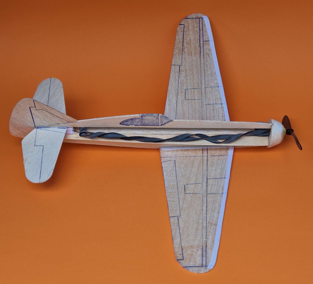
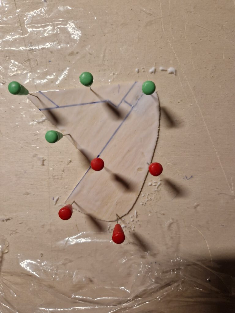
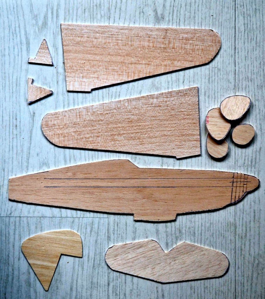
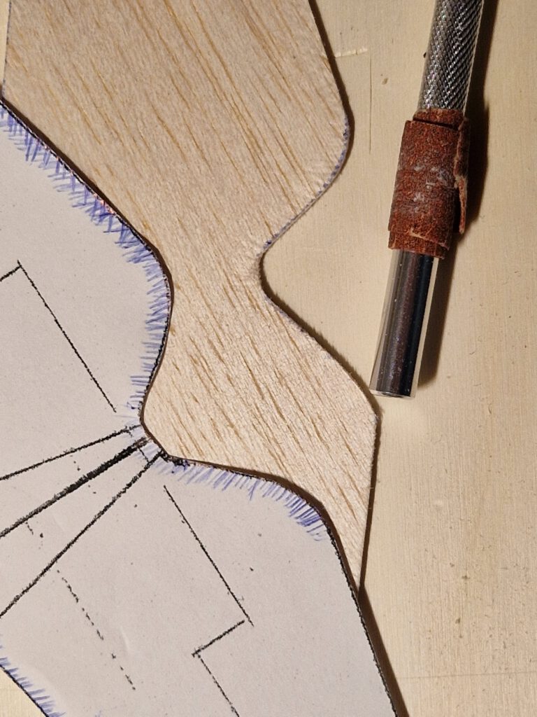
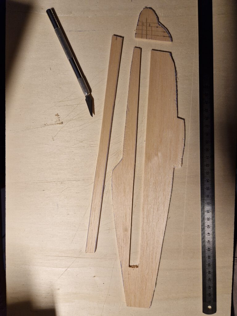
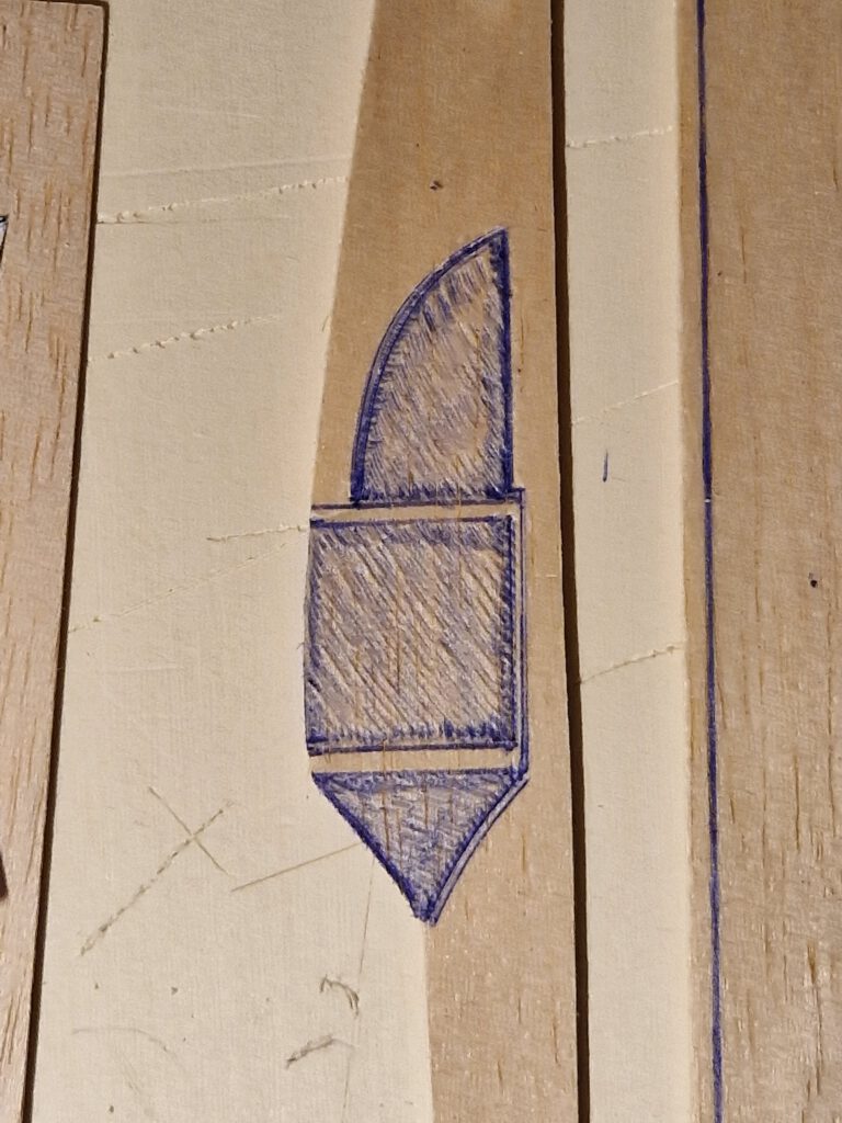
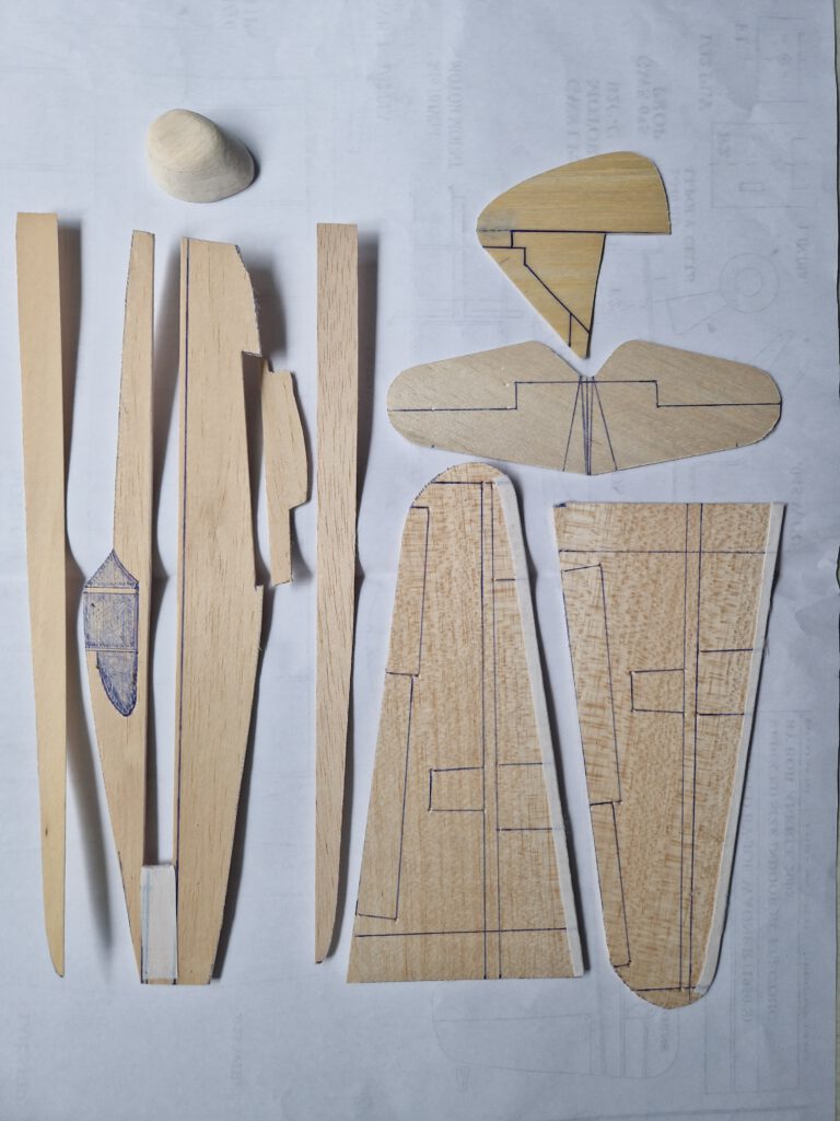
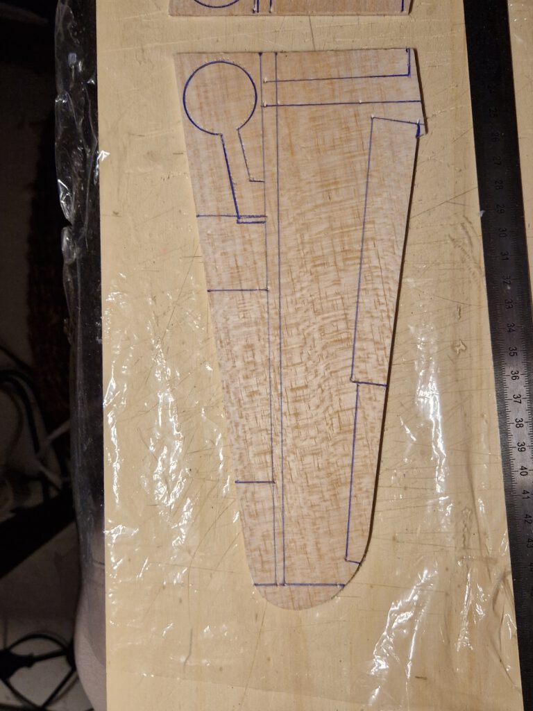
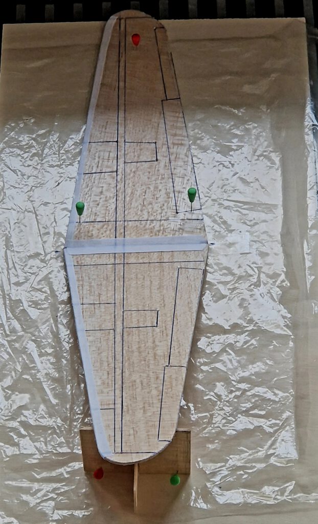
Cut out balsa parts in accordance to plan. Sand well. Transfer outlines of cockpit windows, rudders, elevators, flaps ec. from paper to wood with pen (photo).
Wing:
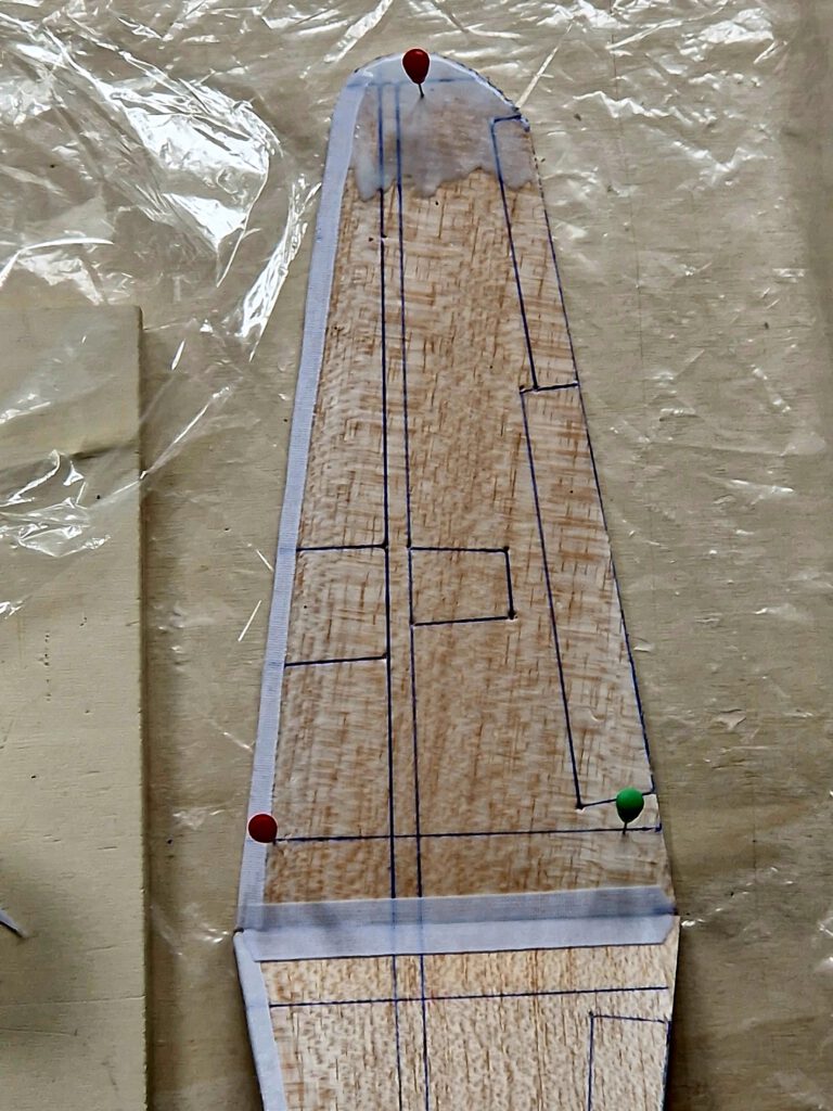
Wing consists of a right and a left wing half. Reinforce both wing half leading edges with linen band. Let dry. Fix right wing half on building board with needles. Underlay left wing half tip in accordance to required dihedral. Join both halves and cover wing center area with linen band (photo). Let dry. If wing has the tendency to rest only on one side then it is too heavy on this side. To compensate the imbalance disperse an amount of white wood glue on the opposite wing half’s tip area (photo). Do it if necessary twice until balance is obtained.
Fuselage:
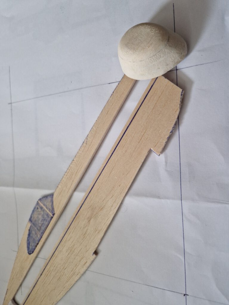
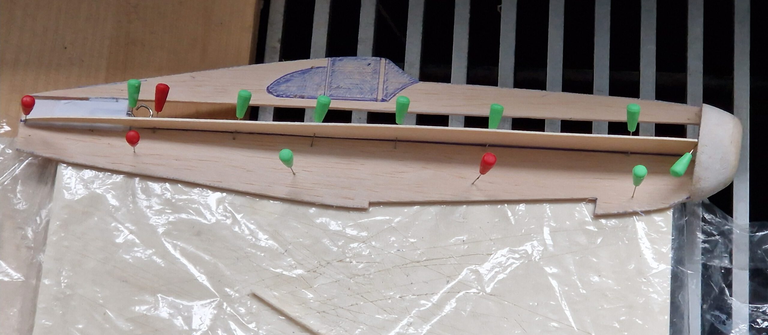
Bend as shown on plan piano wire into given hook shape. Carve out with knife and round file seat for rubber hook on left or right side of fuselage. Cement hook in place and cover hook area generously with linen band. Let dry. Cement right side stiffener using needles to hold in place. For maintaining right angle (90°) check angle with drawing triangle. Let dry. Turn fuselage around and fix it on one edge of your building board and repeat this procedure on left side (photo). Always visual check twice that symmetry is obtained.
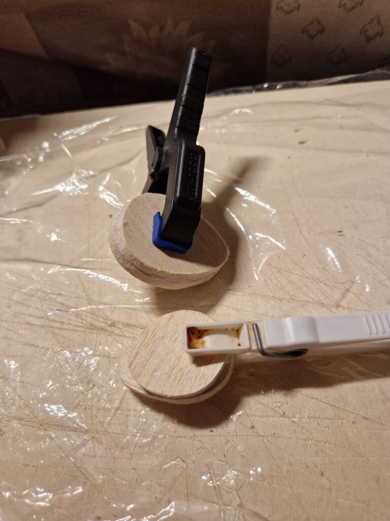
Cement B 5 nose parts one on the other as shown on plan and let dry. Sand well than treat this part with balsa putty. When dry sand again. May be this procedure has to be repeated. When the nose part is smooth you can start to carve out opening which will hold prop-bearing. Start from behind and do it not in a hurry. A little electric drill machine can be useful.
Cement nose on fuselage refering to photos.
Empennage:
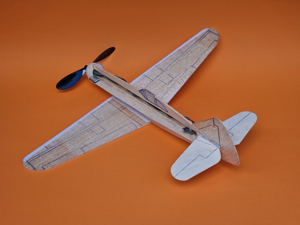
Start with the horizontal stabilizer and cement it into given place. Visual check symmetry from all sides. Let dry. Fin is next. It must sit in the middle of the thicker material of the fuselage and it must stand 100 % upright. So use either clamps or needles to achieve this aim. Again visual check from all sides.
Final Assembly:
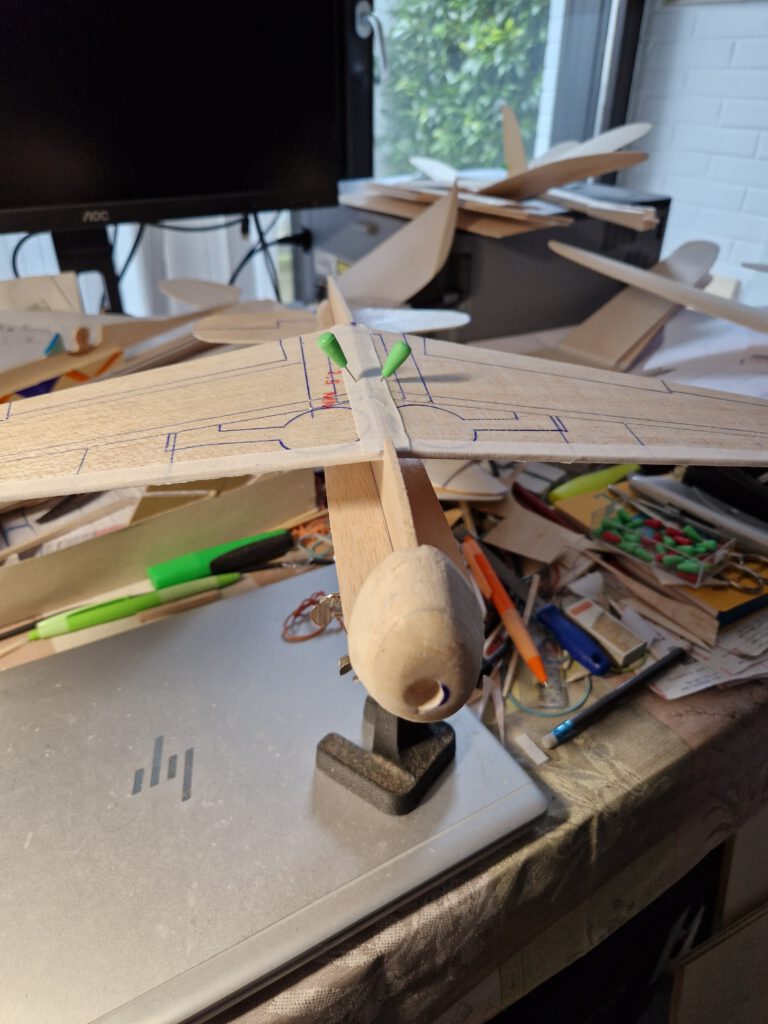
Put fuselage on a so called “third hand” upside down (photo). Cement wing on fuselage using needles to hold in place. Doublecheck visually symmetry. Let dry. Optionally you can now cement the ventral radiator part on top of the still inverted model just as shown on plan.
Use a piece of lead or scrap metal to balance model at given position.
Remember correct center of gravity (CG) is essential for successful flights.
¡Muchos vuelos exitosos! (Size bol başarılı uçuşlar diliyorum!)
Leave a Reply