
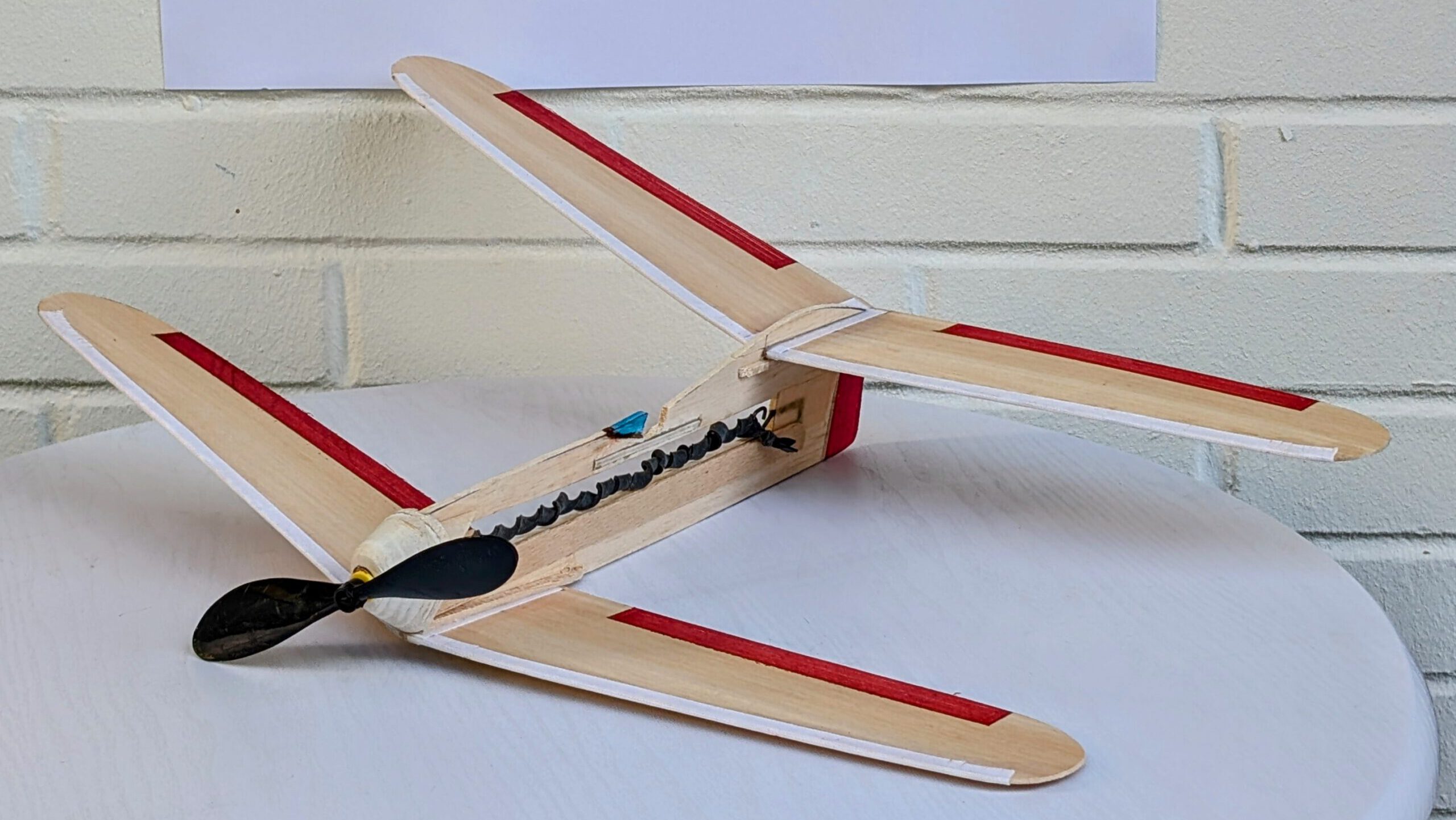
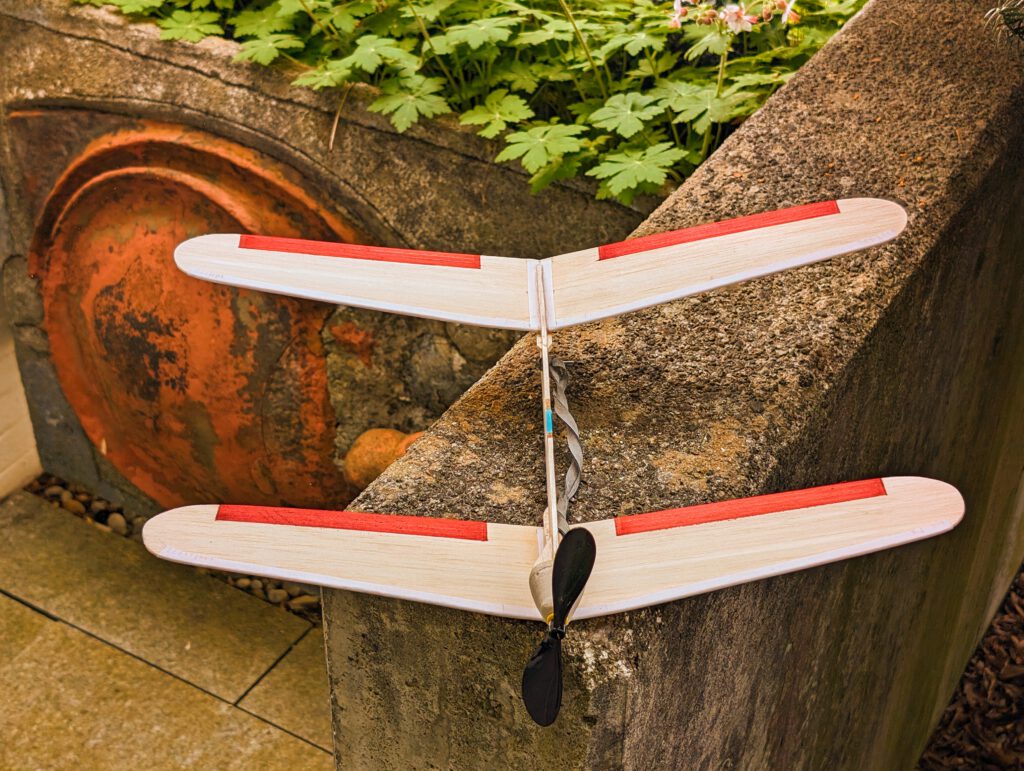
Span 46 cm / 18 in
Weight 52 g / 1.8 oz
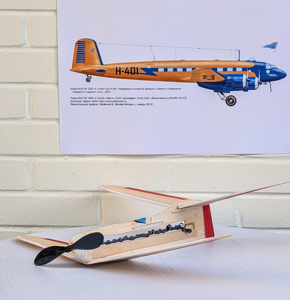
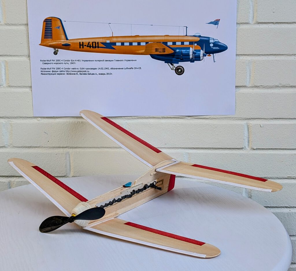
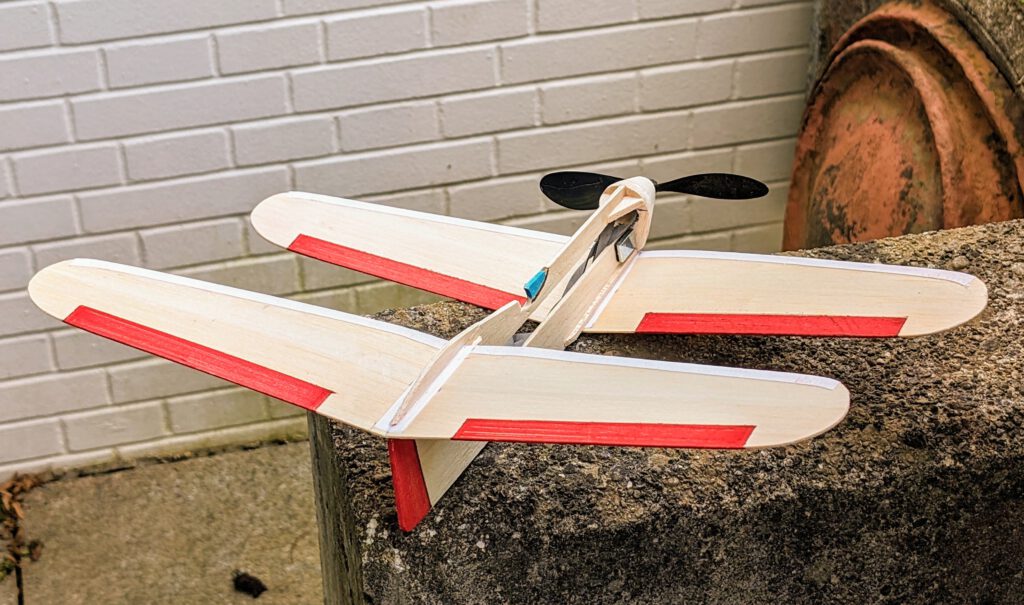
The projected Schehak single seat tandem sports and leisure plane was never built as its designer D. Schehak from Hamburg/Germany died prematurely. A three-view of the plane and some basic information were given in the 19/1937 issue of „Flugsport“ magazine. These drawings were the basis for my model. Powerplant would have been a 20 hp piston engine, further it was planned that the single wheel landing gear would retract into the fuselage.
Note: I built two models of the Schehak tandem, one rubber-powered (here), the other 3010 for use with my RPU 20 power unit.
Building the Schehak tandem single seater model:
Materials:
Fuselage: B 3 or 4; fuselage reinforcement whole length: birchwood or plywood strip strength 1; fuselage nose parts: B 5 or 4 or 3; nose supports (triangles): B 5; rubber hook: piano wire 1.2 or 1.5 mm diameter; wings: B 1.5; wing supports: B strips 3 x 3; linen band width 10 mm / ½ in; ballast: 5 g / 0.2 oz scrap metal or lead; one commercial airscrew 15 cm / 6 in diameter; greyish-black rubber.
Assembly:
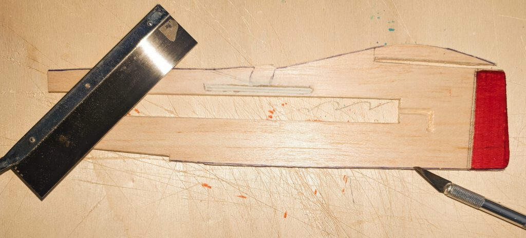
Cut out balsa parts in accordance to plan. Make slot for rear wing and cutout for frontal wing on fuselage. Cutout for open cockpit make at a later phase. Sand well. Transfer outlines of cabin, rudders etc. from paper to wood with pen.
Wings:
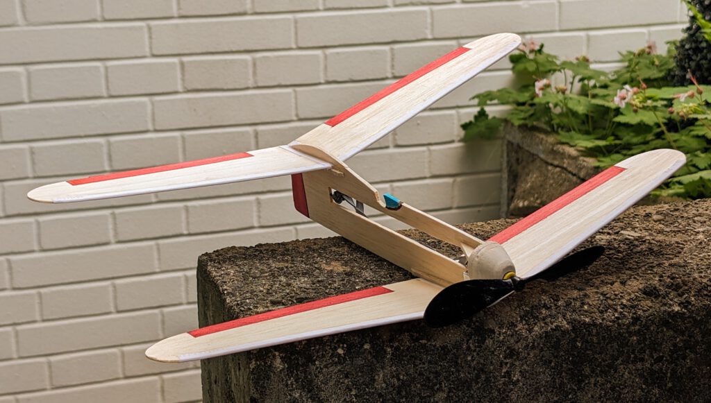
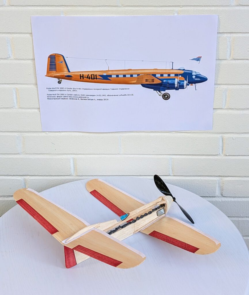
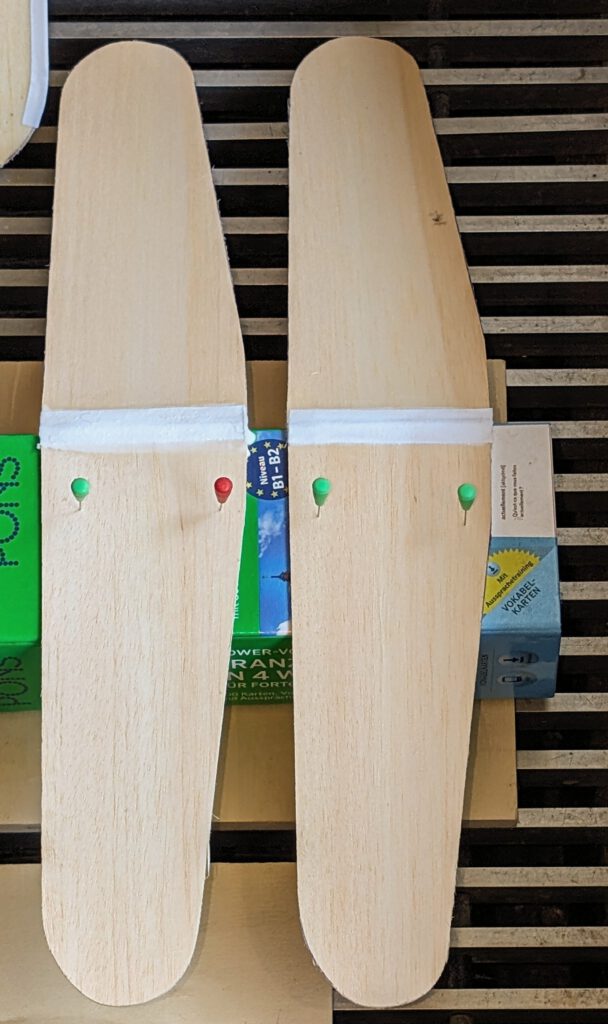
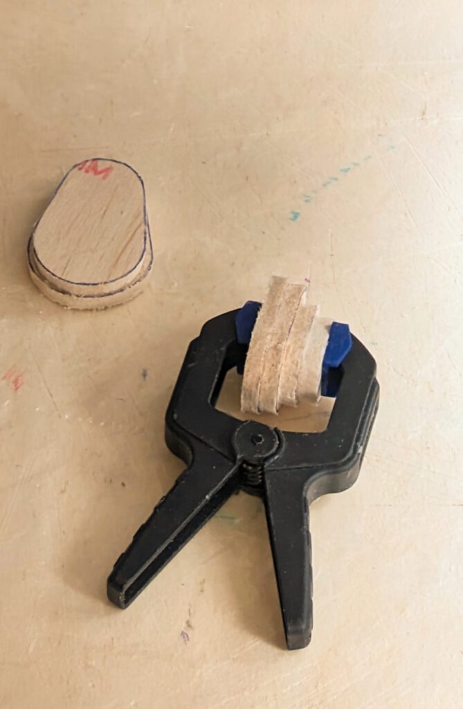
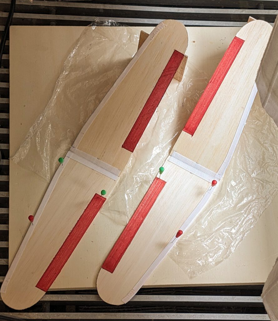
Wings consists of a right and a left wing half each. Reinforce all wing half leading edges with linen band or with a B 1 strip on its underside. Let dry. Fix one wing half on building board with needles. Underlay the corresponding wing half’s tip in accordance to required dihedral (photo). Join halves and cover wing center areas with linen band (photo). Let dry. If a wing has the tendency to rest only on one side it is too heavy on this side. To compensate imbalance disperse an amount of white wood glue on the opposite wing tip area. Do it if necessary twice until balance is obtained.
Fuselage:
(Prototype had an additional reinforcement under open cockpit which can be omitted as whole length plywood reinforcements on both sides provide for enough stability.)
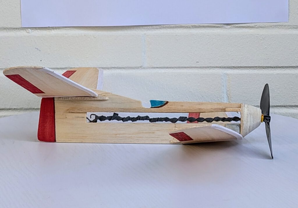
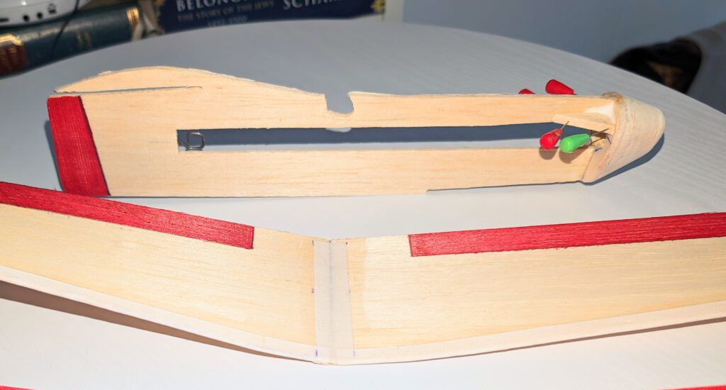
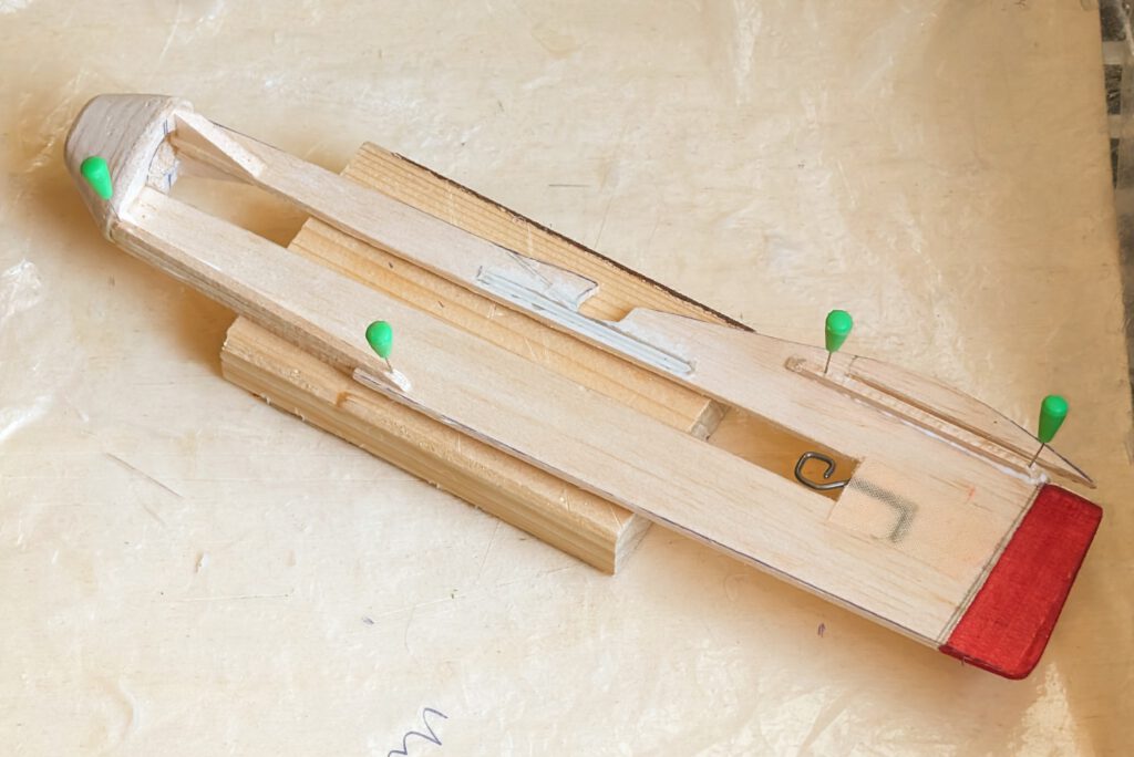
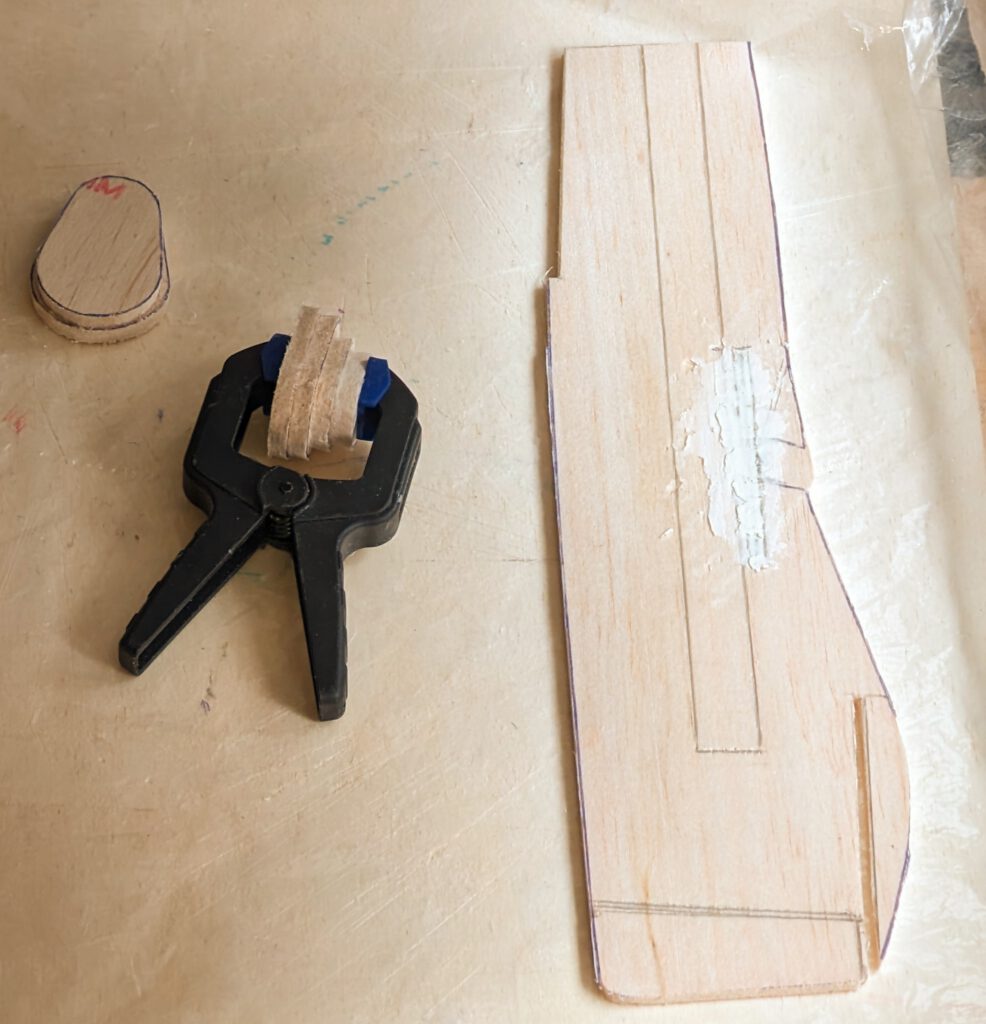
Bend as shown on plan piano wire into given hook shape. Carve out with knife and round file seat for rubber hook on left or right side of fuselage (photo). Cement hook in place and cover hook area generously with glue and linen band. Let dry.
Cement whole length plywood reinforcements on fuselage, either right or left side. (Prototype has upper reinforcement on right side and lower reinforcement on left side.)
Only now make cockpit cutout.
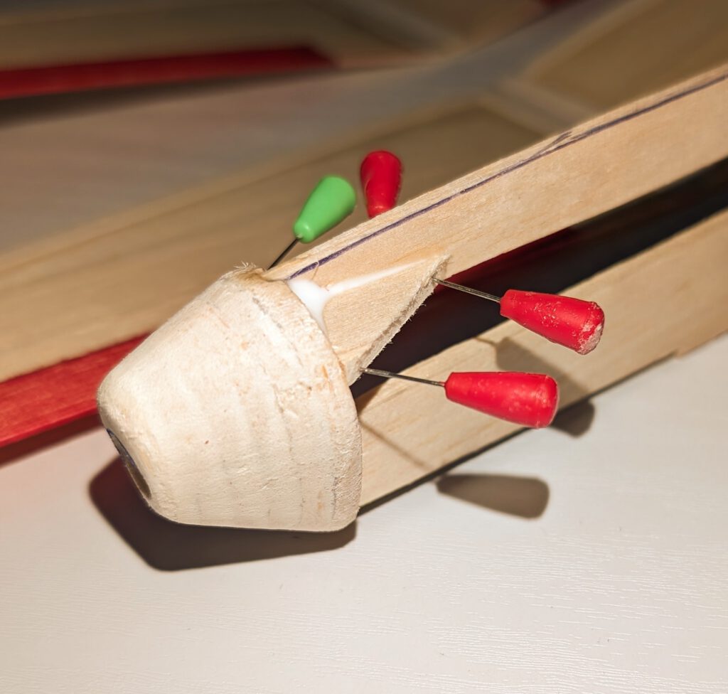
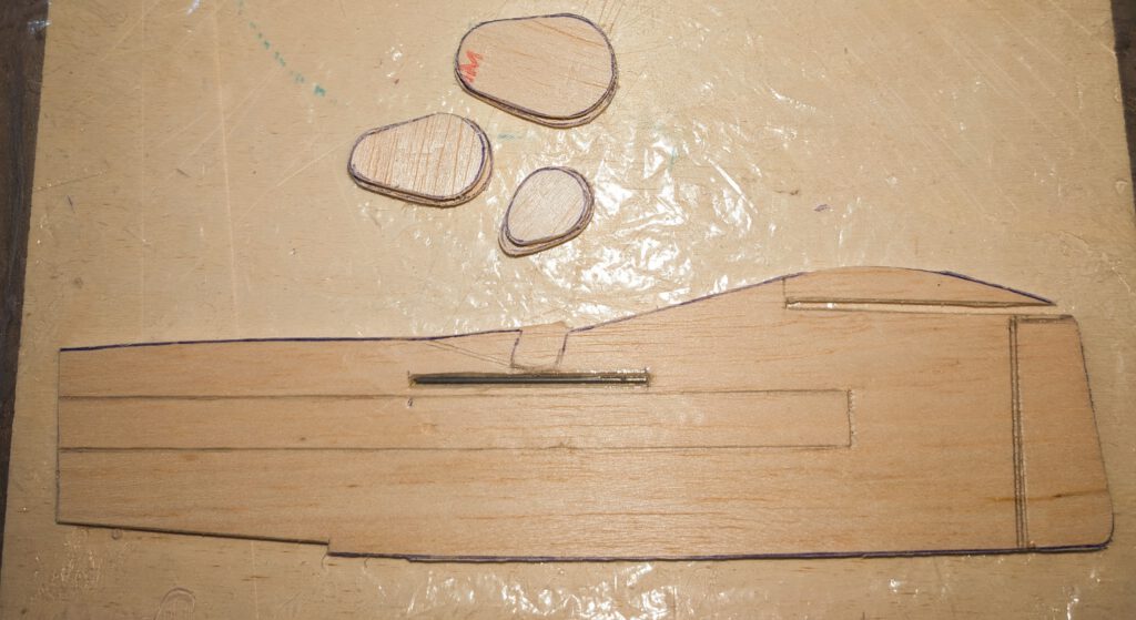
Cement B 5 (or 4 or 3) nose parts one on the other as shown on plan and let dry. Sand well than treat this part with balsa putty. When dry sand again. May be this procedure has to be repeated. When the nose part is smooth you can start to carve out opening which holds prop-bearing. Start from behind and do it not in a hurry. A little electric drill machine can be useful.
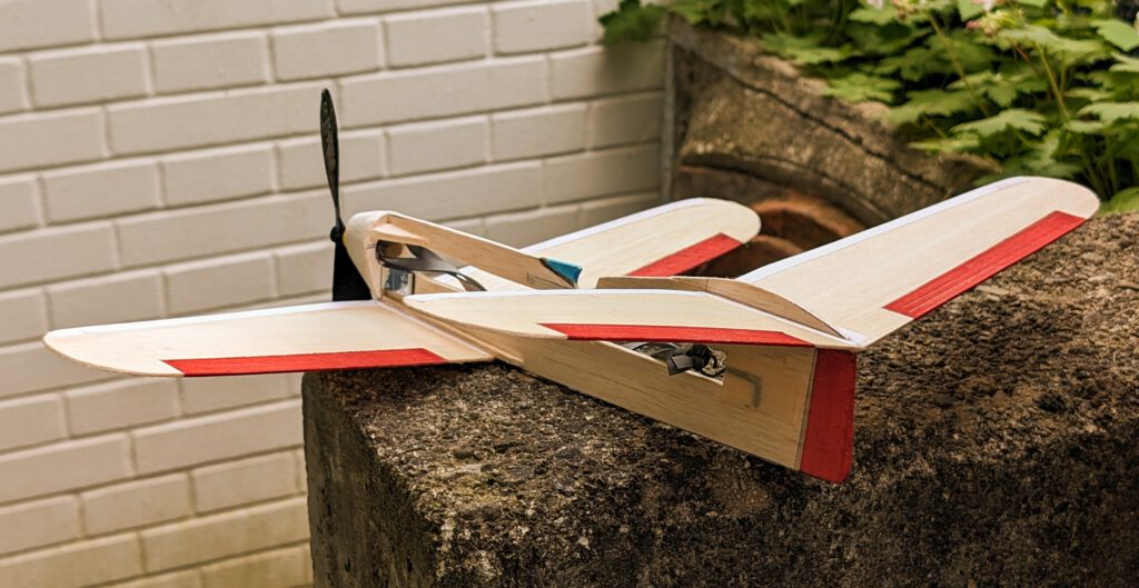
Cement nose on fuselage referring to photos. When dry add nose support balsa triangles (photo).
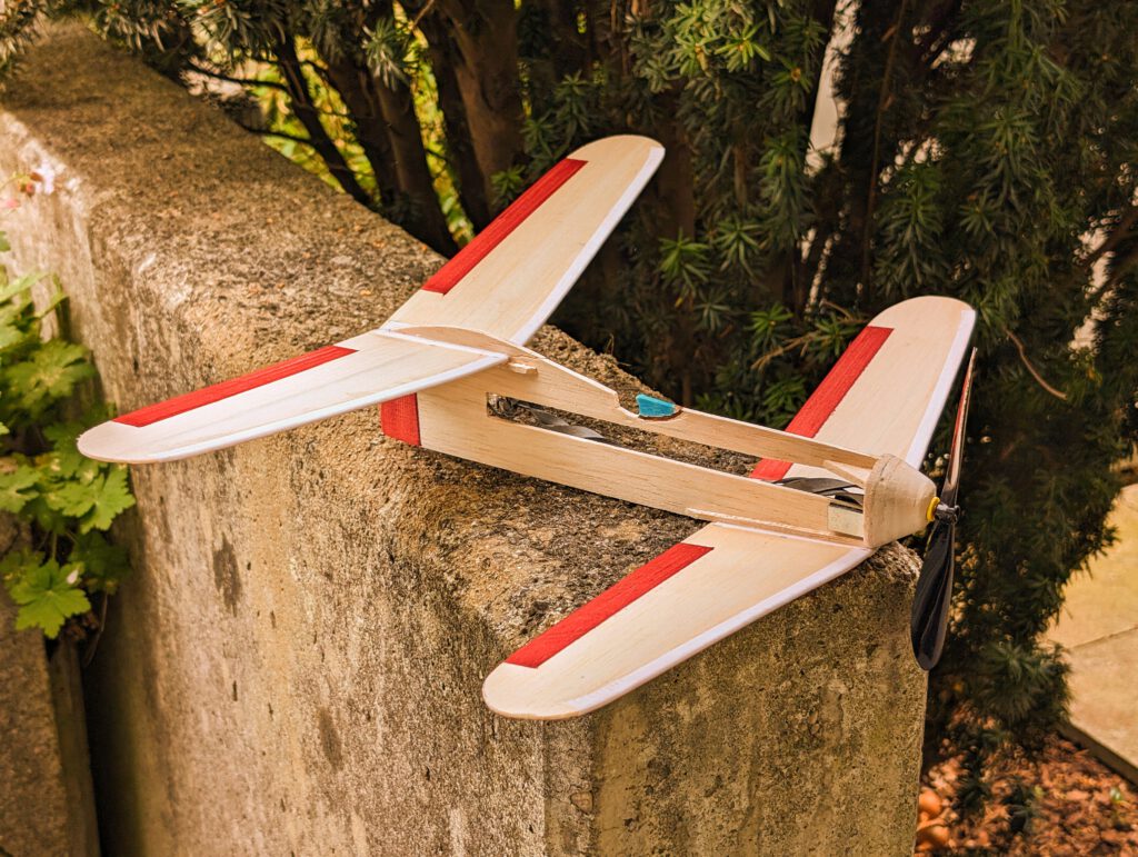
Cement wing support strips as shown on photo and plan. Hold with needles or clamps in place.
Final Assembly:
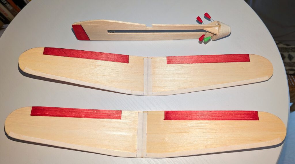
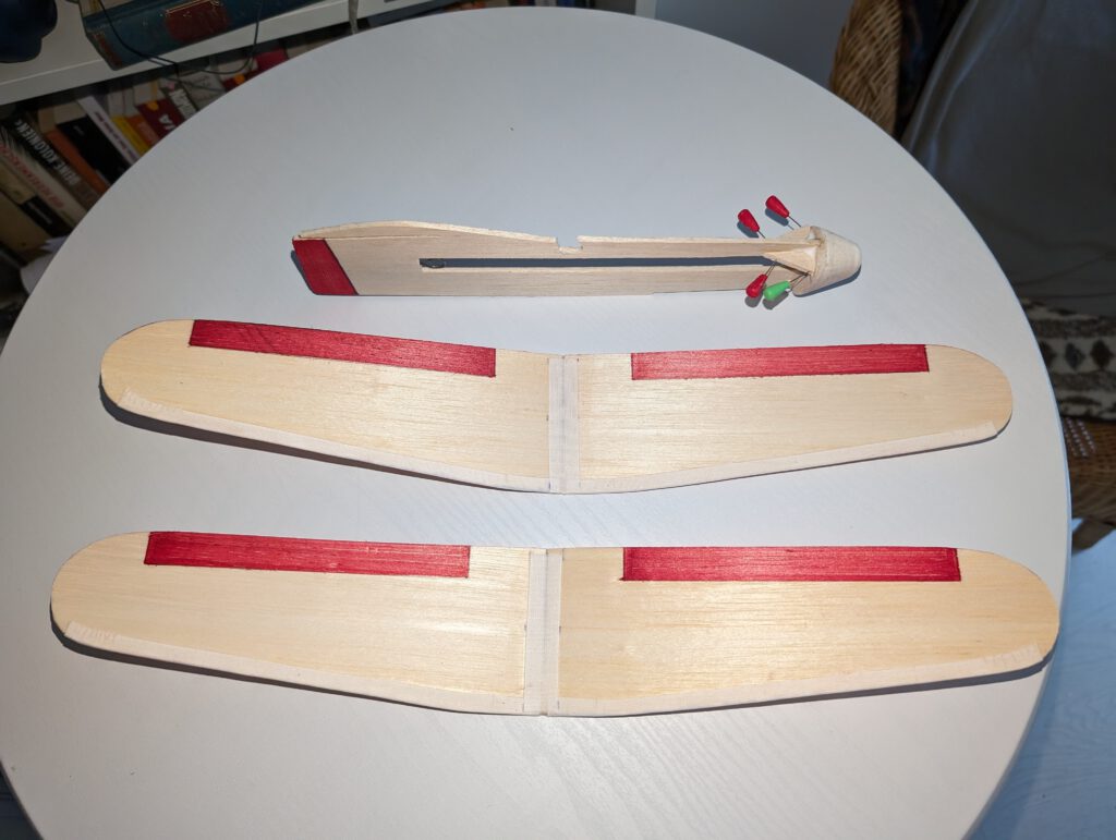
Put fuselage on a so called “third hand”. Cement rear wing in slot and on fuselage supports using needles to hold in place. Doublecheck visually symmetry. Let dry. Now attach your model upside down on “third hand” and repeat procedure with frontal wing.
Use a piece of lead or scrap metal to balance model at given position.
Remember correct center of gravity (CG) is essential for successful flights.
Size bol başarılı uçuşlar diliyorum! (Přeji mnoho příjemných letů!)

Leave a Reply