
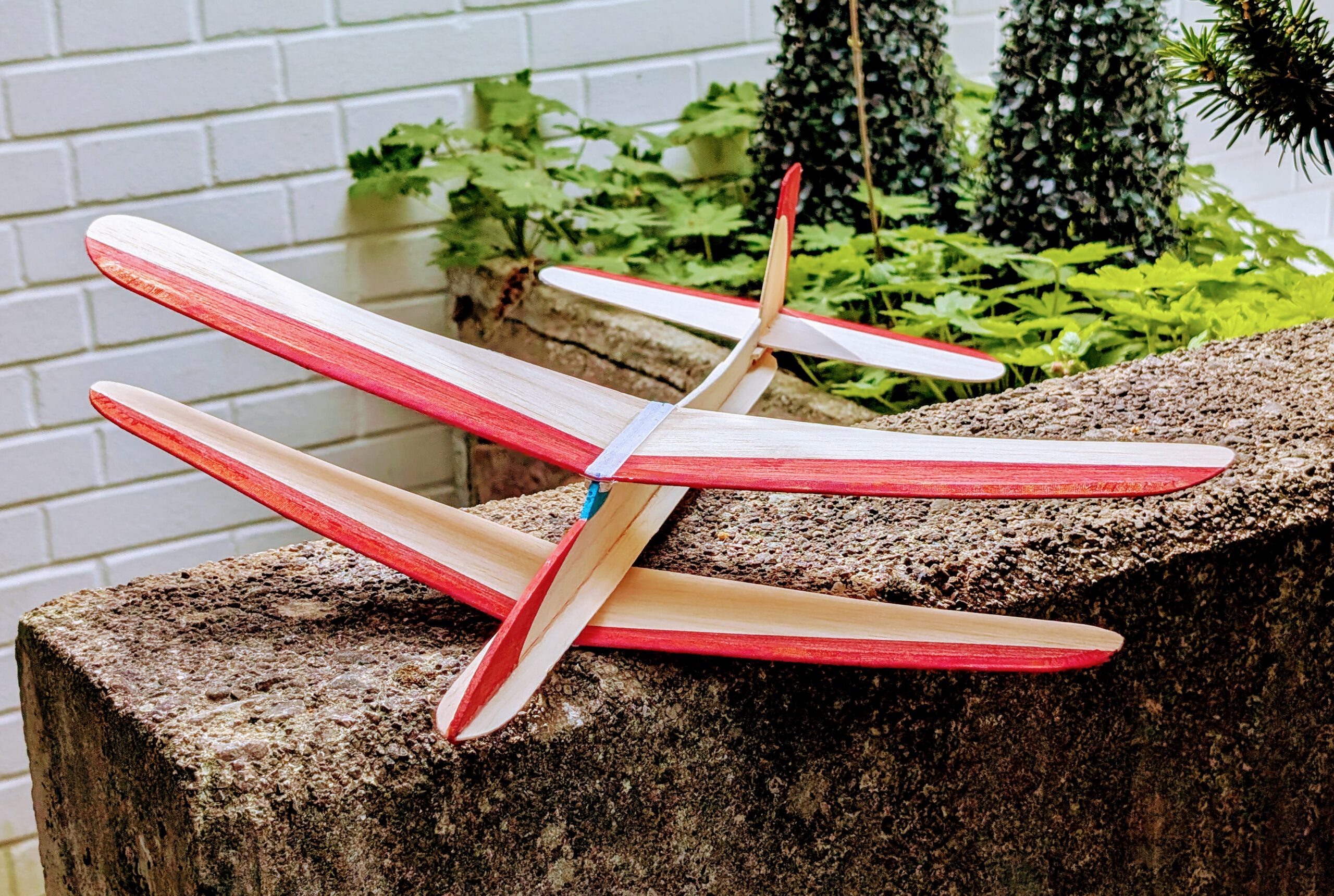


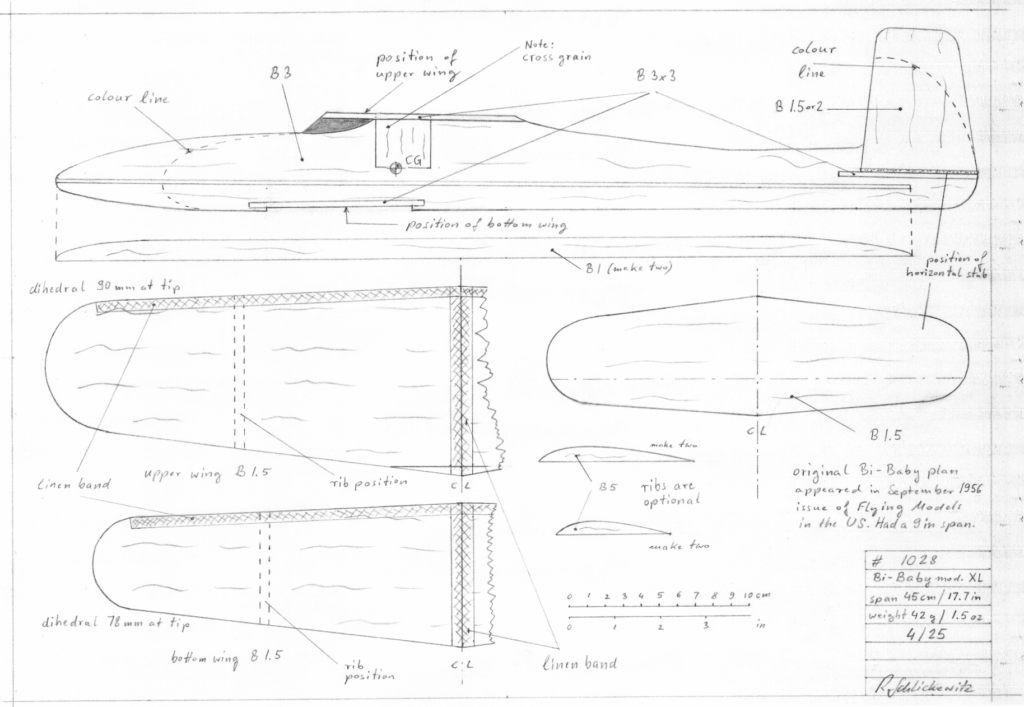
Span 45 cm / 17.5 in
Weight 42 g / 1.5 oz
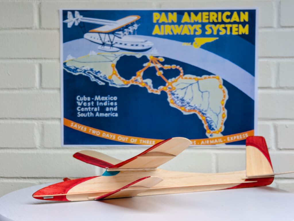
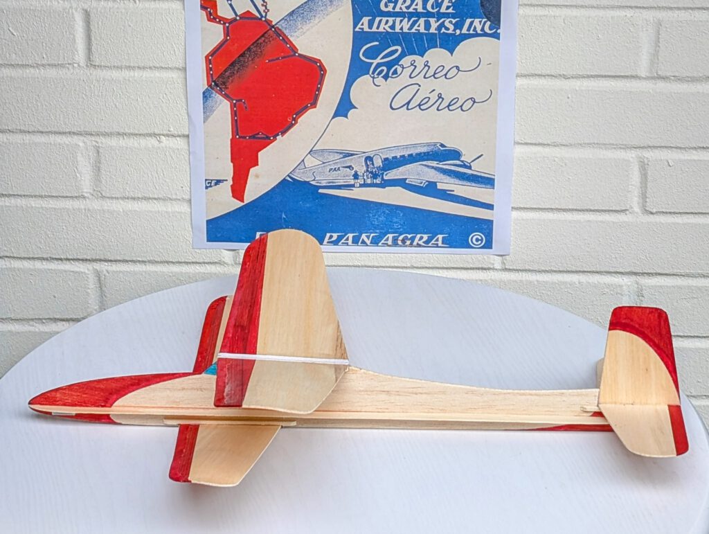
The original Bi-Baby was published in the September 1956 issue of “Flying Models”. It had a span of 9 in and was intended as a simple small chuck glider. The plan has been enlarged and the design was adjusted to optimally fit the new size. Bi-Baby preserves the classic lines of its era and can therefore be considered part of the cultural heritage of its country of origin, the USA.
Design specifics:
- Simple glider design
- Biplane
- Profiled wings
- Easy to build
- Few parts
Building the sheet balsa chuck glider Bi-Baby mod. XL
Materials:
Fuselage: B 3; fuselage stiffeners: B 1 or 1.5; cross grain piece under upper wing: B 3; wing supports: B strips 3 x 3; horizontal stab supports: B strips 3 x 3; fin: B 1.5 or B 2; wings: B 1.5; wing ribs: B 5; horizontal stab: B 1.5; linen band width ½ in = 12 mm; ballast: steel or lead.
Assembly:
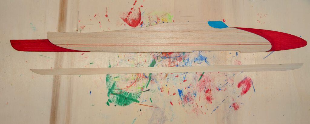
Cut out balsa parts in accordance to plan (photo). Make cutout for lower wing on fuselage part. Sand well. If coloring is desired, what is recommended, do it at this stage.
Wing:
Fix one upper wing half on building board with needles. Cement other half at given dihedral to it (photo). Linen/cotton band should later be cemented on the joining areas on top and bottom (photo). Repeat procedure for lower wing pair. Let thoroughly dry. Cement linen band around leading edge of the wing so that band forms a U around the leading edge. Let dry. Now cement wing ribs into their given positions (photo). This step can be omitted, it is optional.
Fuselage:
Fix fuselage with needles on building board. First glue cross grain part to fuselage and let dry. Then cement one side stiffener at given position (photo). Let dry. Turn fuselage assembly around and have it sit on two larger pieces of hardwood or on two books or on two bricks of equal size, always the side stiffener between them. Glue the other side stiffener on assembly and secure it with needles/pins. Let dry. This procedure can also be done on one edge of your building board – see photo.
Cement wing and horizontal stab support strips on left side in place and secure with needles/pins. When dry, repeat this procedure on the right fuselage side. Let dry.
Empennage:
Cement fin on horizontal stab at an exact 90-degree angle (photo). Secure with pins and let dry.
Final Assembly:
Put fuselage on so called third hand (photo). Set empennage assembly on its support strips and assure that absolute symmetry is obtained. If not, sand down a little balsa on one of the support strips. Cement and let dry (photo).
Do same procedure with upper wing (photo) and when dry with lower wing. Always visual check better twice than once to obtain best possible symmetry.
Strengthen nose area on all sides with some extra glue. Disperse glue well and let entirely dry.
Start test flying over grass when a piece of lead or scrap metal as ballast (photo) is installed.
Remember correct center of gravity (CG) is essential for successful flights.
שיהיו טיסות נעימות! (passez des vols agréables!)


Reproduction of the plan – reduced size
Leave a Reply