

Span 53 cm / 20.9 in
Weight 55 g / 1.9 oz


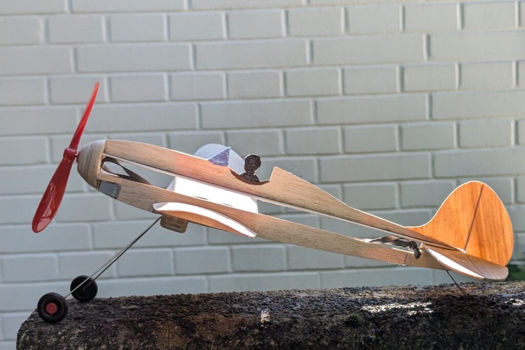
The concept:
- vintage outlines
- good flight characteristics
- low-wing monoplane
- detachable landing gear
- profiled wing
- more power through a bigger airscrew
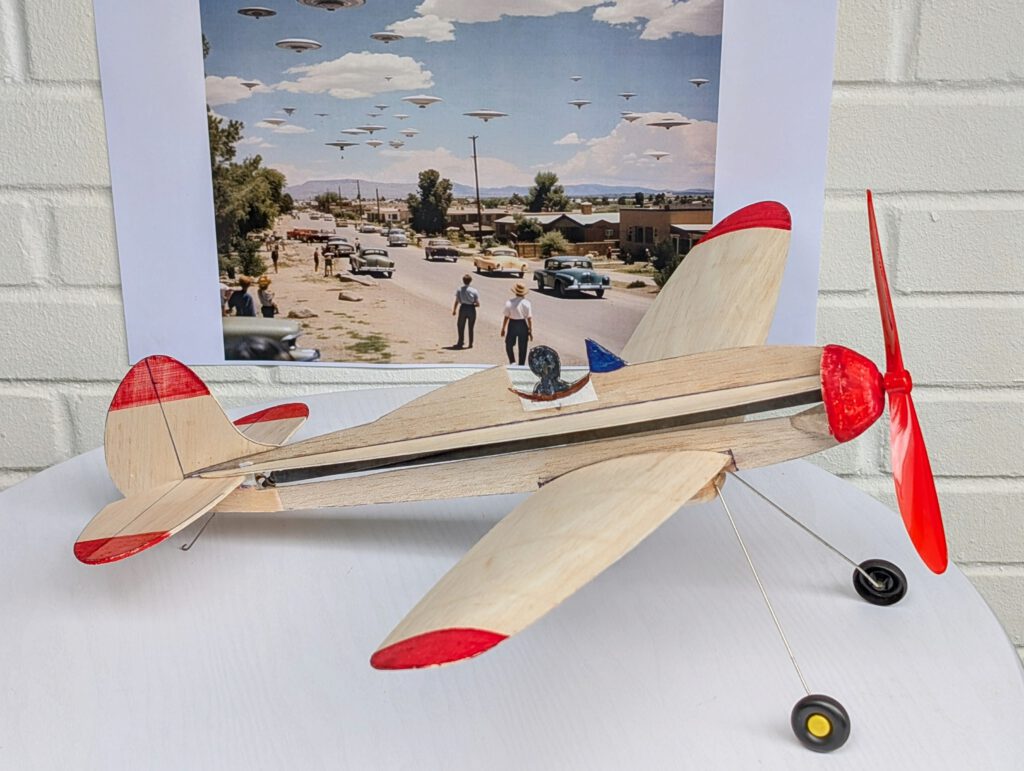
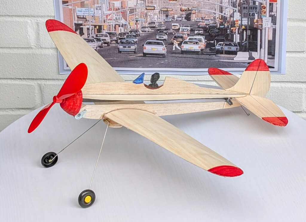
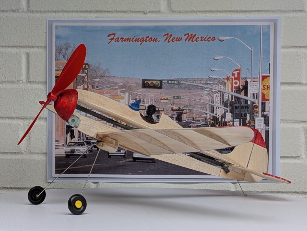
Name is intended to remind of a pleasant small town in the southwest with a real nice sheriff, an interesting history and an impressive landscape around. Fairytale-like is the way this model flies. Try it yourself.
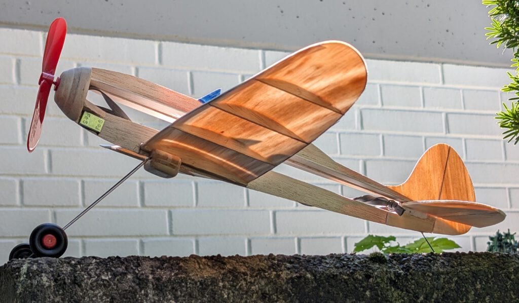
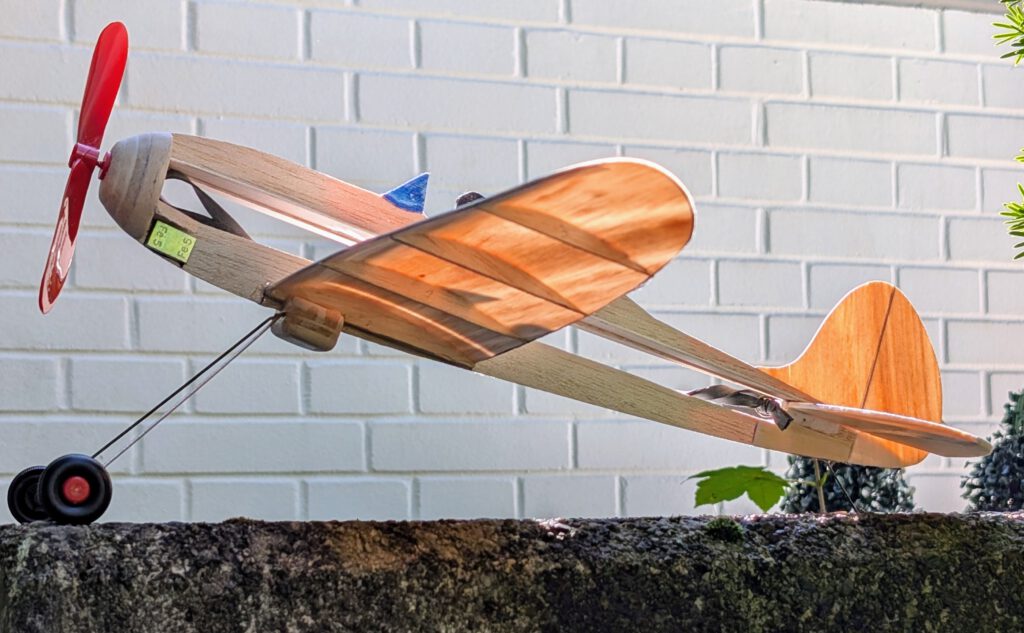
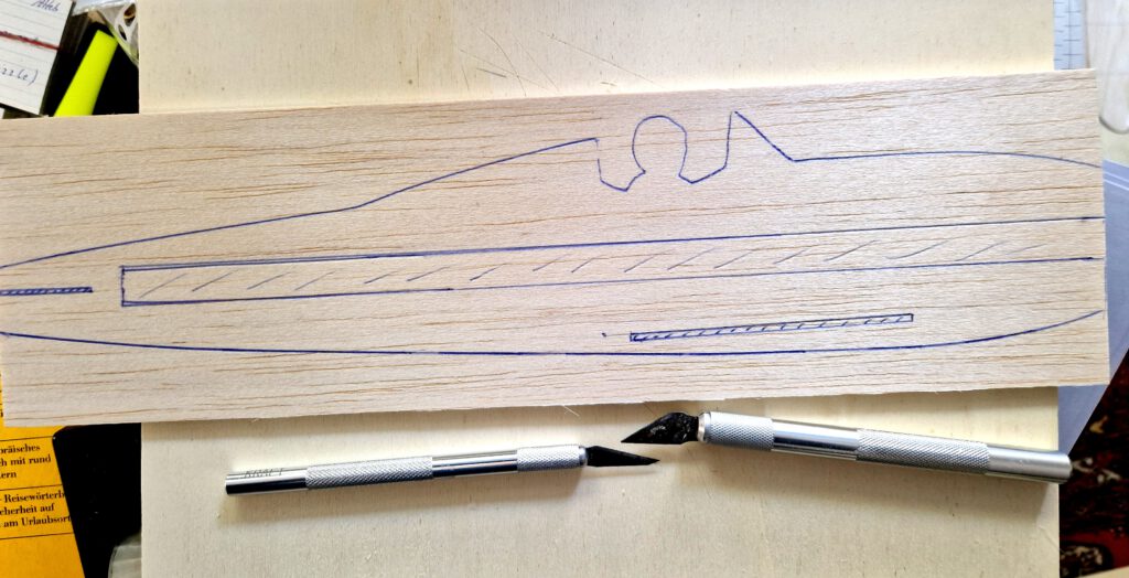
Building the rubber powered balsa profile-fuselage model Farmington Fairytale.
Materials
Fuselage: B 3 or 4; fuselage side stiffeners: B 1; fuselage nose parts: B 4 or 5; rubber hook: piano wire 1.2 mm diameter; wings: B 1 or 1.5; wing root ribs: B 5; other ribs B 1 or 1.5; horizontal stabilizer: stiff B 1.5 or soft 2.5; fin: B 1 or 1.5; tail skid: plywood or piano wire 1.2 mm diameter; landing gear parts: B 4 and 5 plus hardwood 2; linen band width 12 mm / ½ in; ballast: small piece of scrap metal or lead; one commercial airscrew 7 in diameter; black rubber; one commercial small model landing gear with 1 or 1.5 in diameter light wheels or self-made lg from 1.2 mm diameter piano wire according to plan.
Assembly
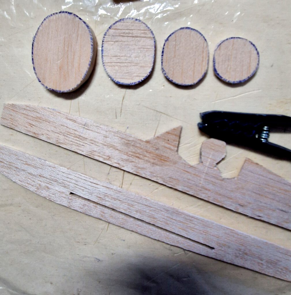
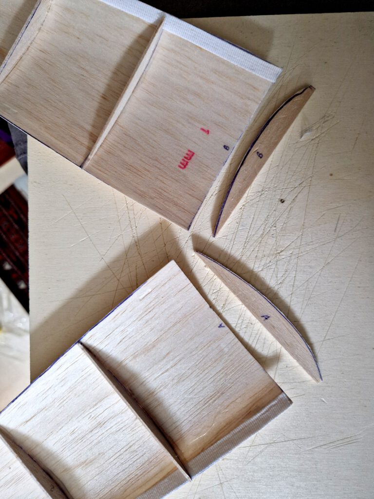
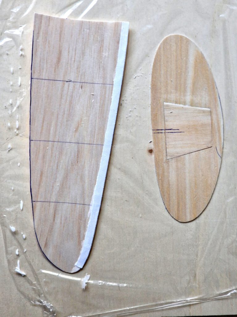
Cut out balsa parts in accordance to plan. Sand well (photo). Transfer outlines of windshield, rudders, elevators, etc. from paper to wood with pen. If desired paint model parts now.
Wing:
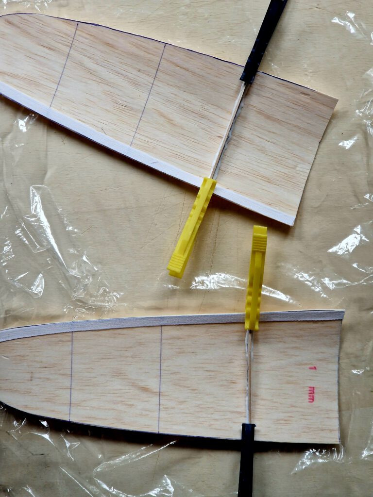
Cement linen band around leading edges of both wing halves so that band forms a U around the leading edge. Let dry.
Sand upper surfaces of both root ribs a bit oblique. Pin one root rib on your building board. Underlay corresponding wing’s tip at the indicated height and cement wing half on rib. Use plenty of pins to hold in place. Repeat this procedure for the other wing. Let dry.
Install all other ribs as shown on plan. Use clamps.
Now put each wing half on a small kitchen scale. If there is a weight difference, disperse a small amount of white glue near the tip of the lighter wing half’s underside and disperse it well. Do this if necessary twice until equilibrium is reached.
Fuselage:
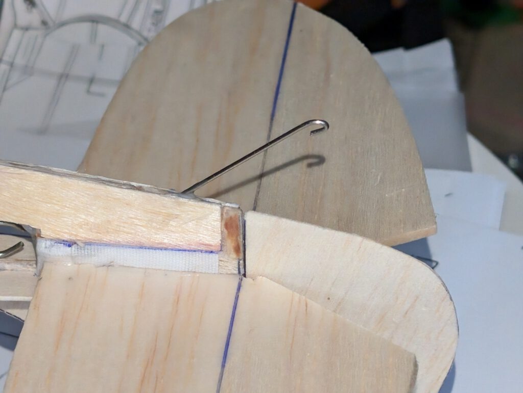
Bend as shown on plan piano wire into given hook shape. Carve out with knife and round file seat for rubber hook on left or right side of fuselage. Cement hook in place and cover hook area with linen band as seen on photos. Let dry.
Cement optional hardwood pilot silhouette in place. Let dry.
Install first one fuselage side stiffener only and let dry. Repeat procedure with stiffener on other side.
Make up your mind what you want to use, a commercial landing or a self-made-one. Then see details for either undercarriage installation on plan and described in other chapters below.
Cement B 5 nose parts one on the other as shown on plan and let dry. Sand well than treat this part with balsa putty. When dry sand again. May be this procedure has to be repeated. When the nose part is smooth you can start to carve out opening which will hold prop-bearing. Start from behind and don’t do it in a hurry. A little electric drill machine can be useful.
Cement nose on fuselage according to plan and photos. When dry add elongated B 5 additional fuselage side stiffeners, one on each side, as shown on plan. Installing this part is recommended no matter what kind of lg you choose.
Empennage:
Cement horizontal stabilizer into its slot on fuselage using pins to hold. Visual check symmetry from all sides. Let dry.
Add fin in the same way and let dry.
Commercial landing gear:
Cement parts one on the other as shown on plan and let dry. Round corners of lg-assembly into streamlined shape. Insert slit for commercial landing gear of your choice. Let in some drops of Superglue to strengthen slit walls as material should withstand more frequent use. Cement assembled balsa block on fuselage cutout. Visual check symmetry from all sides and let dry.
Self-made landing gear:
Bend piano wire according to pattern on plan. It is easier than you might think, just start to do it with the help of two needle nose pliers. Drill little holes into the hull as shown on plan. Sew the wire tight to the fuselage with a solid thread. Cover area around generously with epoxy. Let dry.
Final Assembly:
Cement one wing half on fuselage at the position given on plan using strong clamps to hold in place. Doublecheck visually symmetry and dihedral. Let dry.
Repeat procedure for the other wing half and let entirely dry.
Install tail skid.
A piece of lead or scrap metal may be used to balance model if necessary. My model was balanced correctly without any ballast a I use a rather heavy prop.
Remember correct center of gravity (CG) is essential for successful flights.
Palju edukaid lende! (Molts vols d’èxit!)

Leave a Reply